Description
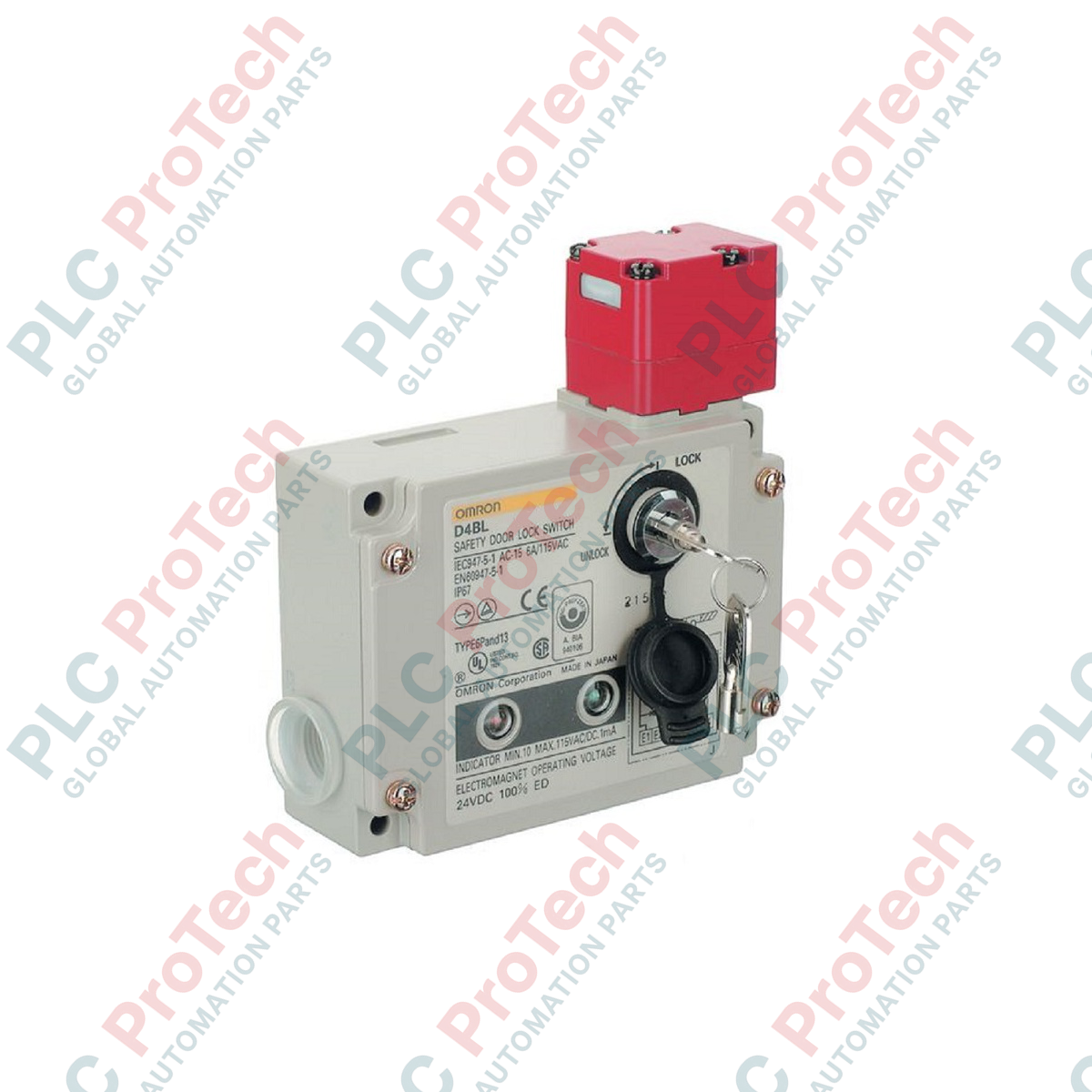
Securing heavy-duty industrial access gates and hazardous machinery enclosures, the Omron D4BL-2CRA is an industrial-grade safety interlock switch engineered with a robust mechanical lock and 24 VDC solenoid release mechanism. Built to comply with rigorous international safety standards, this device features a dual-conduit configuration and multiple contact outputs to guarantee dependable door monitoring and system-wide safety integration.
This switch functions as a Type 2 interlock device under EN ISO 14119, utilizing a low-level coded actuator key design. To prevent accidental entrapment or lockouts during power failures, an auxiliary release key is integrated directly into the rugged housing, enabling manual release by authorized maintenance personnel. Its robust mechanical build achieves an IP67 rating, ensuring reliable operation in harsh environments contaminated with dust, debris, and low-pressure water sprays.
Features
-
Fail-Safe Mechanical Lock: Employs a physical mechanical locking principle that secures the actuator key upon insertion, requiring 24 VDC solenoid energization to release.
-
Multi-Contact Output: Outfitted with 1NC/1NO door open/closed detection contacts alongside a dedicated 1NC lock monitor switch contact, both executing via slow-action mechanics.
-
Flexible Head Orientation: Adjustable head mechanism allows up to four distinct mounting directions, optimizing alignment options during system deployment.
-
Auxiliary Override: Integrated auxiliary release key enables manual unlocking for maintenance procedures or emergency overrides.
-
G1/2 Conduit Ports: Dual-conduit entry structure simplifies wiring layouts and separating power lines from control signals.
Applications
-
Automotive Assembly Lines: Secures robotic cell enclosures where entry must be prohibited until automated cycles completely cease.
-
Machining Centers: Installed on safety gates of high-speed CNC milling, turning, and grinding machinery to prevent access during spindle deceleration.
-
Packaging & Palletizing Zones: Prevents operators from entering dangerous moving conveyor paths and automated strapping zones.
-
Heavy Industrial Mixers: Ensures material loading doors remain locked until mixing paddles are verified to be at a complete standstill.
Technical Specifications
| Parameter |
Specification Value |
| Manufacturer |
Omron |
| Model Designation |
D4BL-2CRA |
| Interlock Type |
Type 2 (EN ISO 14119) |
| Locking Principle |
Mechanical Lock / Solenoid Release |
| Solenoid Rated Voltage |
24 VDC |
| Coding Level |
Low Level coded (EN ISO 14119) |
| Conduit Outlets |
G1/2 (2-conduit design) |
| Built-in Contacts Configuration |
1NC/1NO (door monitoring) + 1NC (lock monitoring), slow-action |
| Electrical Durability |
500,000 operations minimum (10 A resistive load at 250 VAC) |
| Mechanical Durability |
1,000,000 operations minimum |
| Operating Speed Range |
0.05 to 0.5 m/s |
| Maximum Operating Frequency |
30 operations per minute |
| Ingress Protection Rating |
IP67 (EN60947-5-1) |
| Device Weight |
0.8 kg |
| Shipping Weight |
2.0 kg |
Empirical Engineering Insights
Alternative Models & Compatibility
The D4BL-2CRA is a mechanical-lock/solenoid-release variant, meaning it relies on spring force to lock the gate and 24 VDC power to release it. In applications where immediate egress during a power failure is a safety requirement, mechanical-lock models are highly preferred because they stay physically locked unless overridden by the mechanical override key. This contrasts with solenoid-lock models (such as the D4BL-2GRA) which unlock immediately upon power loss, a behavior that may be dangerous in processes with long run-down times.
Application Pitfalls & Engineering Notes
During system integration, ensure that the solenoid coil is not continuously energized for prolonged periods exceeding the design parameters, as continuous excitation will cause thermal stress. Use PLC logic to pulse the release coil only when the machine has reached zero-speed verification, and drop the energization signal once the gate open status is confirmed.
Commissioning & Wiring Tips
Physical actuator misalignment is the primary cause of premature switch failure. When mounting, ensure that the mechanical gate has physical door stops installed. The safety switch must never be used as a mechanical stop; crashing forces will warp the key entry head, leading to failure of the lock monitoring contacts. Conduit connections should be sealed with proper cable glands to maintain the IP67 integrity.
Installation Guidelines
CRITICAL WARNING
Disconnect and isolate all control circuit power before attempting installation, adjustment, or physical wiring of this device. Verify that the machinery has completely stopped and that no kinetic or thermal energy remains stored in the cell before working on the safety barrier.
1
Adjust the head orientation by loosening the head assembly screws, rotating the head to your desired target axis (right-side mounting is active by default), and securing the screws tightly to preserve the IP67 seal.
2
Mount the switch housing securely to the stationary frame of the safety guard using M5 screws, ensuring the surface is flat to prevent structural torque on the switch body.
3
Align and mount the companion actuator key to the moving door or gate, verifying that the key enters smoothly into the center of the slot without catching or applying side-load pressure.
4
Complete all electrical connections via the G1/2 conduit ports, wiring the 1NC lock monitoring and 1NC/1NO door safety contacts into your safety relay or safety PLC input module.