Description
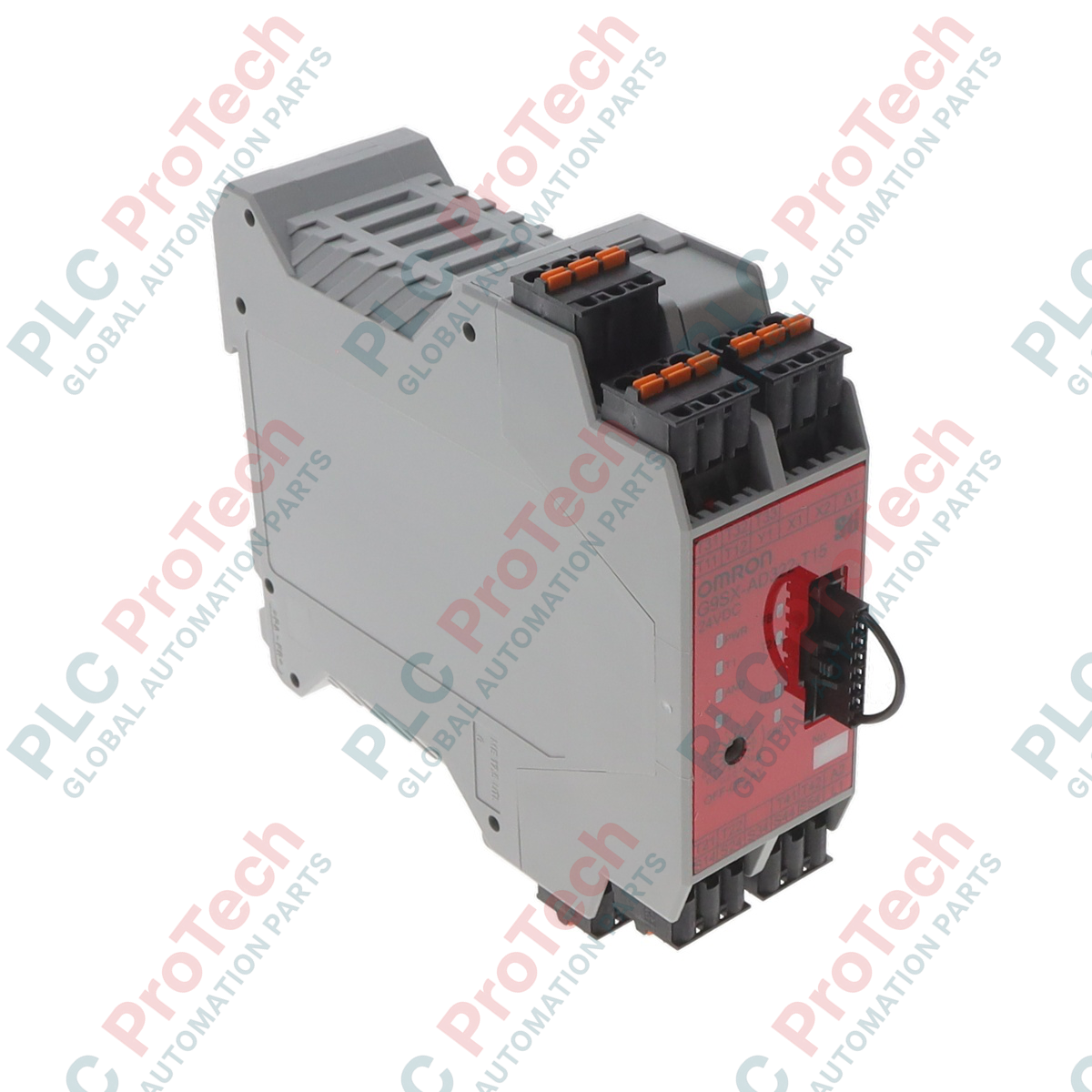
Managing complex safety control loops across automated machinery requires robust logic processing, which the Omron G9SX-ADA222-T15-RC Advanced Safety Unit executes with solid-state precision. This flexible safety controller integrates logical AND connection functions to facilitate advanced safety networking across distributed modules without the need for a safety PLC. Outfitted with high-speed P-channel MOS FET transistor outputs, it delivers long operational life and eliminates the mechanical wear associated with traditional relay-based safety units.
Designed for flexible safety architectures, this device provides instantaneous and configured OFF-delayed outputs, supporting complex stop category requirements. The inclusion of modern spring-cage terminal blocks ensures reliable electrical contact under severe industrial vibrations, making it an ideal choice for high-vibration manufacturing and assembly environments.
Features
-
Advanced Logical Functions: Supports logical AND connections to link multiple safety units for coordinated stop sequences.
-
Dual Solid-State Output Types: Equipped with 2 instantaneous safety outputs and 2 OFF-delayed safety outputs for precise machine stop control.
-
Configurable OFF-Delay: Features a selectable OFF-delay timer adjustable up to 15 seconds.
-
Spring-Cage Terminals: Releasable spring-cage connection technology reduces wiring time and prevents loose connections caused by mechanical vibration.
-
Comprehensive Diagnostics: Integrated LED status indicators simplify troubleshooting by displaying safety input, feedback, and internal system error codes.
Applications
-
Robot Cells: Coordinated monitoring of emergency stop circuits, light curtains, and safety door interlocks.
-
High-Vibration Machinery: Packaging, material handling, and automotive assembly lines where terminal screw loosening is a hazard.
-
Multi-Zone Production Lines: Complex interlocked safety zones requiring logical AND connectivity between local guard circuits.
Technical Specifications
| Parameter |
Specification |
| Manufacturer |
Omron |
| Model Number |
G9SX-ADA222-T15-RC |
| Device Type |
Advanced Safety Unit |
| Rated Supply Voltage |
24 VDC |
| Operating Voltage Range |
-15% to 10% of rated supply voltage (20.4 to 26.4 VDC) |
| Power Consumption |
4 W max. |
| Instantaneous Safety Outputs |
2 semiconductor outputs (P-channel MOS FET) |
| OFF-Delayed Safety Outputs |
2 semiconductor outputs (P-channel MOS FET) |
| Auxiliary Outputs |
2 semiconductor outputs (PNP transistor, 100 mA max.) |
| Max. OFF-Delay Time |
15 seconds |
| Output Load Current (Safety) |
Using 2 outputs or less: 1.0 A DC max. / Using 3 outputs or more: 0.8 A DC max. |
| Safety Input Impedance |
Approx. 2.8 kohms |
| Terminal Connection Type |
Spring-cage (tension clamp) |
| Vibration Resistance |
10 to 55 to 10 Hz, 0.375-mm single amplitude (0.75-mm double amplitude) |
| Weight |
0.2 kg |
| Shipping Weight (Calculated) |
1.5 kg (including structural export packaging) |
Empirical Engineering Insights
Based on field commissioning experiences, several critical system-level factors should be accounted for during design and deployment:
Alternative Models & Compatibility
The "RC" in the model designation indicates spring-cage terminals. If replacing an older "RT" screw-terminal version, the internal logical circuit, diagnostics, and auxiliary output wiring configurations remain completely identical. This allows for a direct hot-swap of the unit body if maintaining the same base wiring layout, but require verifying terminal header compatibility.
Application Pitfalls & Engineering Notes
Because safety outputs are solid-state P-channel MOS FETs, they exhibit a small OFF-state leakage current. When interfacing these safety outputs with highly sensitive PLC digital inputs or micro-relays, ensure the input load draws enough current to pull the voltage below the downstream device's OFF threshold. Additionally, when using multiple units in close proximity within unventilated panels, keep a 10 mm lateral gap to prevent heat build-up when running at maximum auxiliary and safety output current ratings.
Commissioning & Wiring Tips
When configuring logical AND connections between multiple G9SX units, ensure the communication lines linked to L1 and L2 terminals are properly shielded and kept away from high-voltage motor cables to avoid noise-induced safety trips. Ensure the feedback and reset loop (terminals T31, T32 for manual reset, or T31, T33 for auto reset) has verified contact continuity before energizing the module; a startup mismatch will trigger an internal loop fault, locking out the unit.
Installation Guidelines
CRITICAL WARNING: ELECTRICAL HAZARD
Always isolate all primary power distribution circuits and auxiliary supply voltages before mounting, wiring, or configuring safety systems. Solid-state outputs can retain charge under specific circuit failure modes. Verify zero potential on all terminals before commencing physical maintenance.
1
Snap-mount the G9SX module onto a standard 35 mm symmetric DIN rail (IEC/EN 60715), ensuring the locking clip is securely engaged.
2
Insert pre-stripped or ferruled 24 AWG to 16 AWG signal cables directly into the spring-cage terminals. Press the orange release buttons with a flat screwdriver if wire adjustment is required.
3
Configure the rotary switches on the front face of the unit to define the target OFF-delay time (up to 15 seconds) prior to applying 24 VDC power.
4
Power on the module and execute a function test of all interconnected guard loops, emergency buttons, and feedback monitoring circuits to confirm correct operation.