ABB

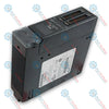
ABB IMDSI14 Bailey INFI 90 Digital Input Module

SKU IMDSI14

Disponibile
  • 12-month warranty
  • Free returns within 30 days
  • Manufacturer: ABB
  • Product No.: IMDSI14
  • Origin Switzerland
  • Product Type: Digital Input Module
  • Barcode: 8537101190
  • Payment: T/T, Western Union
  • Weight: 0.5 kg
  • Dimensions: 28 mm x 178 mm x 298 mm (W x H x D)
  • Shipping port: Xiamen
  • Warranty: 12 months

Tags

Product Documentation

Technical Datasheet (PDF) Complete specifications and technical drawings.

Technical Datasheet

ABB IMDSI14 Bailey INFI 90 Digital Input Module

Quantità

Product Description

The ABB IMDSI14 Bailey INFI 90 Digital Input Module is a 16-channel process interface designed to bring 48 VDC discrete field signals into the Symphony Enterprise Management and Control System for process monitoring and control functions. Fully compatible with INFI 90 OPEN Strategic Enterprise Management Systems, the IMDSI14 links field-level digital contacts directly to a Harmony rack controller over a high-speed parallel I/O expander bus. The device conditions, filters, and isolates incoming process input signals via current limiters and optocouplers, providing up to 1500 VDC electrical isolation between system logic power and high-voltage field wiring. Front-panel LED diagnostics offer point-by-point visual status verification for real-time monitoring and fault isolation within industrial automation architectures.

Features

  • Features 16 distinct digital input channels configured specifically for 48 VDC signal levels.
  • Provides 1500 VDC isolation between field signals and internal logic circuits using optocouplers and current limiters.
  • Incorporates a fixed 17 ms hardware debounce filter to eliminate contact chatter on field input switches.
  • Includes 16 front-panel status LED indicators divided into Group A and Group B for immediate visual channel verification.
  • Utilizes a custom integrated gate array to handle address decoding, function code latching, and I/O expander bus protocol.
  • Integrates directly into standard Module Mounting Units (MMU) occupying a single rack slot.

Applications

  • Distributed Control Systems (DCS) process monitoring
  • Discrete field contact and switch state sensing
  • Heavy industrial automation and plant control systems
  • Power generation, chemical processing, and material handling systems

Technical Specifications

Property Specification
Manufacturer ABB / Elsag Bailey
Input Channels 16 discrete channels (Group A and Group B)
Nominal Operating Voltage 48 VDC (±10%)
Nominal Input Current 4.5 mA
Minimum Turn-On Voltage 26.7 VDC
Maximum Turn-Off Voltage 13 VDC
Minimum Turn-On Current 2 mA at 26.7 VDC
Maximum Off-Leakage Current 50 nA (at Vin≤10.5 VDC)
Response Time 17 ms (fixed debounce filter)
Logic Power Requirements 95 mA at 5 VDC typical, 115 mA maximum
Isolation Voltage 1500 VDC isolation between input and logic circuitry
Mounting Occupies 1 slot in standard Module Mounting Unit (IEMMU11, IEMMU12, IEMMU21, IEMMU22)
Operating Temperature 0 degC to 70 degC (32 degF to 158 degF) internal cabinet rating
Relative Humidity 5% to 95% up to 55 degC, noncondensing; 5% to 45% at 70 degC, noncondensing
Air Quality ISA S71.04 Class LA, LB, LC Level 1 (Noncorrosive)
Atmospheric Pressure Sea level to 3 km (1.86 miles)

Connections/Interfaces

Connector Pin Function
P1 Pin 1, 2 +5 VDC Logic Power
P1 Pin 5, 6 Common / Ground
P1 Pin 3, 4, 7-12 Not Connected (NC)
P2 Pin 1-8 Expander Bus Data Lines (Data 0 through Data 7)
P2 Pin 9 Expander Bus Clock Signal
P2 Pin 10 Expander Bus Sync Signal
P2 Pin 11, 12 Not Connected (NC)
P3 Group A (Input 1-6) Pins A-F (+), Pins 1-6 (-)
P3 Group A (Input 7, 8) Pin H (+ Common), Pin J (Input 8 -), Pin 7 (Input 7 -)
P3 Group B (Input 1-6) Pins K-R (+), Pins 9-14 (-)
P3 Group B (Input 7, 8) Pin S (+ Common), Pin 15 (Input 7 -), Pin 8 (Input 8 -)

Installation Guidelines

  • ESD Protection: Wear a grounded wrist strap connected to an appropriate ground point when handling the board to prevent electrostatic discharge damage. Store in static-shielding bags when not installed.
  • Address Selection: Configure the 8-position DIP switch (S1) prior to physical insertion. Positions 3 through 8 determine the 6-bit binary module address (0 to 63) to match Function Code 84 configuration; positions 1 and 2 must remain closed.
  • Bus Termination: Verify that an I/O expander bus dipshunt is properly seated in the MMU backplane socket between the module and controller before insertion.
  • Physical Insertion: Align the printed circuit board with the guide rails in the card cage slot. Slide the assembly inward until the front panel fits flush against the mounting unit frame and seats securely into the edge connectors.
  • Fastening: Secure the module by turning the two front panel captive retaining screws one-half turn until the slots are vertical and facing toward the center.

Compliance and Certifications

  • CE Mark Directives: EMC Directive 89/336/EEC (EN 50081-2 Generic Emission, EN 50082-2 Generic Immunity), Low Voltage Directive 73/23/EEC (EN 61010-1).
  • CSA Certified: Certified for use as process control equipment in ordinary (nonhazardous) locations.
  • FM Approved (Pending): Nonincendive for Class I, Division 2, Groups A, B, C, D; Class II, Division 2, Groups F, G.
Shipping & Returns

Global Express Shipping

  • Standard Delivery: 4–6 business days via DHL, FedEx, and UPS.
  • Express Dispatch: Same-day dispatch for in-stock orders placed before 2:00 PM (GMT+8).
  • Worldwide Coverage: Serving over 150 countries.

Returns & Warranty

  • 30-Day Guarantee: Returns accepted for in-stock products in original, factory-sealed packaging.
  • 12-Month Warranty: Every industrial component is backed by our technical warranty.
FAQ
What power supply voltage is required to operate the module logic?
The module requires +5 VDC logic power supplied through the P1 backplane edge connector, drawing a typical current of 95 mA and a maximum of 115 mA.
How is the module address configured for system communication?
The address is set using positions 3 through 8 of the 8-position DIP switch (S1) to create a binary address from 0 to 63, which must match the address defined in Function Code 84 of the controller setup.
What is the response time for discrete input signals?
The device features a fixed hardware debounce filter providing a nominal response time of 17 milliseconds to eliminate contact bounce from field switches.
Reviews

IMDSI14

Stock & lead time on request

Call
1 su 3

ABB IMDSI14 Bailey INFI 90 Digital Input Module

Only 5 item(s) left in stock
  • Manufacturer: ABB

  • Product No.: IMDSI14

  • Country of origin:Switzerland

  • Product Type: Digital Input Module

  • Barcode: 8537101190

  • Payment: T/T, Western Union

  • Weight: 500g

  • Dimensions: 28 mm x 178 mm x 298 mm (W x H x D)

  • Shipping port: Xiamen

  • Warranty: 12 months

Quantità
Visualizza dettagli completi

Product Description

The ABB IMDSI14 Bailey INFI 90 Digital Input Module is a 16-channel process interface designed to bring 48 VDC discrete field signals into the Symphony Enterprise Management and Control System for process monitoring and control functions. Fully compatible with INFI 90 OPEN Strategic Enterprise Management Systems, the IMDSI14 links field-level digital contacts directly to a Harmony rack controller over a high-speed parallel I/O expander bus. The device conditions, filters, and isolates incoming process input signals via current limiters and optocouplers, providing up to 1500 VDC electrical isolation between system logic power and high-voltage field wiring. Front-panel LED diagnostics offer point-by-point visual status verification for real-time monitoring and fault isolation within industrial automation architectures.

Features

  • Features 16 distinct digital input channels configured specifically for 48 VDC signal levels.
  • Provides 1500 VDC isolation between field signals and internal logic circuits using optocouplers and current limiters.
  • Incorporates a fixed 17 ms hardware debounce filter to eliminate contact chatter on field input switches.
  • Includes 16 front-panel status LED indicators divided into Group A and Group B for immediate visual channel verification.
  • Utilizes a custom integrated gate array to handle address decoding, function code latching, and I/O expander bus protocol.
  • Integrates directly into standard Module Mounting Units (MMU) occupying a single rack slot.

Applications

  • Distributed Control Systems (DCS) process monitoring
  • Discrete field contact and switch state sensing
  • Heavy industrial automation and plant control systems
  • Power generation, chemical processing, and material handling systems

Technical Specifications

Property Specification
Manufacturer ABB / Elsag Bailey
Input Channels 16 discrete channels (Group A and Group B)
Nominal Operating Voltage 48 VDC (±10%)
Nominal Input Current 4.5 mA
Minimum Turn-On Voltage 26.7 VDC
Maximum Turn-Off Voltage 13 VDC
Minimum Turn-On Current 2 mA at 26.7 VDC
Maximum Off-Leakage Current 50 nA (at Vin≤10.5 VDC)
Response Time 17 ms (fixed debounce filter)
Logic Power Requirements 95 mA at 5 VDC typical, 115 mA maximum
Isolation Voltage 1500 VDC isolation between input and logic circuitry
Mounting Occupies 1 slot in standard Module Mounting Unit (IEMMU11, IEMMU12, IEMMU21, IEMMU22)
Operating Temperature 0 degC to 70 degC (32 degF to 158 degF) internal cabinet rating
Relative Humidity 5% to 95% up to 55 degC, noncondensing; 5% to 45% at 70 degC, noncondensing
Air Quality ISA S71.04 Class LA, LB, LC Level 1 (Noncorrosive)
Atmospheric Pressure Sea level to 3 km (1.86 miles)

Connections/Interfaces

Connector Pin Function
P1 Pin 1, 2 +5 VDC Logic Power
P1 Pin 5, 6 Common / Ground
P1 Pin 3, 4, 7-12 Not Connected (NC)
P2 Pin 1-8 Expander Bus Data Lines (Data 0 through Data 7)
P2 Pin 9 Expander Bus Clock Signal
P2 Pin 10 Expander Bus Sync Signal
P2 Pin 11, 12 Not Connected (NC)
P3 Group A (Input 1-6) Pins A-F (+), Pins 1-6 (-)
P3 Group A (Input 7, 8) Pin H (+ Common), Pin J (Input 8 -), Pin 7 (Input 7 -)
P3 Group B (Input 1-6) Pins K-R (+), Pins 9-14 (-)
P3 Group B (Input 7, 8) Pin S (+ Common), Pin 15 (Input 7 -), Pin 8 (Input 8 -)

Installation Guidelines

  • ESD Protection: Wear a grounded wrist strap connected to an appropriate ground point when handling the board to prevent electrostatic discharge damage. Store in static-shielding bags when not installed.
  • Address Selection: Configure the 8-position DIP switch (S1) prior to physical insertion. Positions 3 through 8 determine the 6-bit binary module address (0 to 63) to match Function Code 84 configuration; positions 1 and 2 must remain closed.
  • Bus Termination: Verify that an I/O expander bus dipshunt is properly seated in the MMU backplane socket between the module and controller before insertion.
  • Physical Insertion: Align the printed circuit board with the guide rails in the card cage slot. Slide the assembly inward until the front panel fits flush against the mounting unit frame and seats securely into the edge connectors.
  • Fastening: Secure the module by turning the two front panel captive retaining screws one-half turn until the slots are vertical and facing toward the center.

Compliance and Certifications

  • CE Mark Directives: EMC Directive 89/336/EEC (EN 50081-2 Generic Emission, EN 50082-2 Generic Immunity), Low Voltage Directive 73/23/EEC (EN 61010-1).
  • CSA Certified: Certified for use as process control equipment in ordinary (nonhazardous) locations.
  • FM Approved (Pending): Nonincendive for Class I, Division 2, Groups A, B, C, D; Class II, Division 2, Groups F, G.

Product Documentation

Technical Datasheet (PDF) Complete specifications and technical drawings.

Technical Datasheet

ABB IMDSI14 Bailey INFI 90 Digital Input Module

What power supply voltage is required to operate the module logic?

The module requires +5 VDC logic power supplied through the P1 backplane edge connector, drawing a typical current of 95 mA and a maximum of 115 mA.

How is the module address configured for system communication?

The address is set using positions 3 through 8 of the 8-position DIP switch (S1) to create a binary address from 0 to 63, which must match the address defined in Function Code 84 of the controller setup.

What is the response time for discrete input signals?

The device features a fixed hardware debounce filter providing a nominal response time of 17 milliseconds to eliminate contact bounce from field switches.

Global Express Shipping

  • Standard Delivery: 4-6 Business Days via DHL, FedEx, and UPS.
  • Express Dispatch: Same-day dispatch for in-stock orders placed before 2:00 PM (GMT+8).
  • Worldwide Coverage: Serving over 150 countries, including rapid delivery to Saudi Arabia and UAE.

Returns & Warranty

  • 30-Day Guarantee: Returns accepted for in-stock products in original, factory-sealed packaging.
  • 12-Month Warranty: Every industrial component is backed by our professional technical warranty.

Orders are processed and delivered Monday-Friday (excluding public holidays).


For full eligibility, restocking fees, and international return details, please view our official Refund & Return Policy .

TECHNICAL SPECIFICATIONS

Color pattern
Black
Country of origin
Switzerland
Power source
DC Power

Technical knowledge

1756-L73 Firmware Upgrade Guide: v19 vs v21/v31 Decision

Replacing a 1756-L73 does not automatically mean upgrading its firmware. This guide compares v19.013, v21.011 and v31.011, focusing on project compatibility, HMI communications, legacy networks and...

Implementing 3-Switch XOR Ladder Logic with Internal Bit

Implement a 3-SPST switch XOR light circuit in LogixPro or RSLogix 500 using an internal relay bit. Includes truth tables, boolean equations, and verified.

Building a Modbus RTU Network with CompactLogix and DeltaV

Integrate Allen-Bradley CompactLogix, Caterpillar ATS, and generators into DeltaV DCS over Modbus RTU. Covers ProSoft MVI69-MCM, Miille DIN266 gateways.

ONS Instruction Not Energizing OTE in Studio 5000 Ladder Logic

ONS instruction fires but the OTE coil never latches in Studio 5000 because the one-shot is only true for one scan. Use OTL/OTU or seal-in logic instead.

Kinetix 5500 EtherNet/IP Network Switch Requirements and Topology

Configure Allen-Bradley Kinetix 5500 servo drives on EtherNet/IP. Covers CIP Sync, IEEE 1588 V2 timing, Stratix selection, DLR topology, and HMI.

Moving Average Filtering in DCS and PLC Analog Control

A moving-average filter is the sliding-window smoother most instrument engineers drop into DCS and PLC analog paths. Here is how the window works, how N and sample time set lag, and when a...