Allen-Bradley

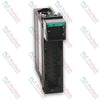
Allen-Bradley 1734-OB4E Point I/O 4-Point Digital Output Module

SKU 1734-OB4E

Disponibile
  • 12-month warranty
  • Free returns within 30 days
  • Manufacturer: Allen-Bradley
  • Product No.: 1734-OB4E
  • Origin Singapore
  • Product Type: Digital Output Module
  • Payment: T/T, Western Union
  • Weight: 0.033 kg
  • Dimensions: 56.6 x 12.1 x 77.5 mm (H x W x D)
  • Shipping port: Xiamen
  • Warranty: 12 months

Tags

Quantità

Product Description

Description

The 1734-OB4E is a 24V DC 4-channel sourcing digital output module designed for use within the Allen-Bradley POINT I/O system. The 1734-OB4E features 4 non-isolated, electronically protected outputs organized into a single group. Operating on a nominal 24V DC external power supply, the module provides short circuit and overload protection for connected field loads. The module interfaces across industrial networks using DeviceNet, PROFIBUS, ControlNet, or EtherNet/IP adapters, making it suitable for distributed I/O applications controlling field devices such as solenoids, relays, and indicators.

Features

  • 4 non-isolated sourcing digital output channels in one group
  • Electronically protected outputs for short circuit and overload conditions
  • Keyswitch position 1 for mechanical keying on compatible terminal bases
  • Logic-driven status indicators including 4 yellow output status LEDs, 4 red output fault LEDs, and 2 green/red module/network status LEDs
  • Removable terminal block (RTB) support allowing module replacement without disturbing field wiring

Applications

  • Distributed I/O processing on DeviceNet and PROFIBUS networks
  • Control system expansion via EtherNet/IP and ControlNet adapters
  • Switching 24V DC industrial loads including actuators, relays, and solenoids
  • Class I Division 2, Zone 2 hazardous location installations

Technical Specifications

Parameter Specification
Manufacturer Allen-Bradley / Rockwell Automation
Model 1734-OB4E
Number of Outputs 4 (1 group of 4), non-isolated, sourcing
On-State Voltage, Min 10V DC
On-State Voltage, Nom 24V DC
On-State Voltage, Max 28.8V DC
On-State Voltage Drop, Max 0.2V DC
On-State Current, Min 1.0 mA per channel
Off-State Leakage, Max 0.5 mA @ 28.8V DC
Output Signal Delay, Off to On / On to Off 0.1 ms max
Output Current Rating, Per Output 1.0 A
Output Current Rating, Max Per Module 3.0 A
Surge Current 2 A for 10 ms, repeatable every 3 s
External DC Power Supply Voltage, Nom 24V DC
External DC Power Voltage Range 10...28.8V DC
External DC Power Supply Current 16 mA
POINTBus Current, Max 75 mA @ 5V DC
Power Dissipation @ 28.8V DC, Max 1.2 W
Thermal Dissipation @ 28.8V DC, Max 4.1 BTU/hr
Isolation Voltage 50V (continuous), reinforced insulation type, tested @ 2500V DC for 60 s field-side to system
Compatible Wiring Base Assemblies 1734-TB, 1734-TBS, 1734-TOP, 1734-TOPS, 1734-TB3, 1734-TB3S, 1734-TOP3, 1734-TOP3S
Keyswitch Position 1
Terminal Base Screw Torque 0.8 N-m (7 lb-in)
Operating Temperature -20...55 degC (-4...131 degF)
Nonoperating Temperature -40...+85 degC (-40...+185 degF)
Relative Humidity 5...95% noncondensing
Operating Vibration 5 g @ 10...500 Hz
Shock, Operating / Nonoperating 30 g / 50 g
Dimensions (H x W x D) 56.6 x 12.1 x 77.5 mm (2.23 x 0.48 x 3.05 in.)
Weight, Approx. 33.17 g (1.17 oz)
UPC 612598205288
Country of Origin Singapore
Estimated Lead Time 5 days
LCA Method ISO 14040/44 compliant
Impact Assessment Method EF 3.0 (Environmental Footprint) ESPR aligned
Database Used Ecoinvent 3.10
Use Phase Electricity European Average Grid Mix (EU-40)
Cradle To Gate 3.73E+00 kg CO2 eq
Cradle To Grave 7.14E+01 kg CO2 eq


Connections/Interfaces

Connector Pin Function
0 Channel 0 Output Terminal (Out 0)
1 Channel 1 Output Terminal (Out 1)
2 Channel 2 Output Terminal (Out 2)
3 Channel 3 Output Terminal (Out 3)
4 Common Terminal (C)
5 Common Terminal (C)
6 Common Terminal (C)
7 Common Terminal (C)

Installation Guidelines

  • DIN Rail Grounding: Ground the module through the DIN rail to chassis ground using zinc-plated chromate-passivated steel DIN rail (Allen-Bradley part number 199-DR1; 46277-3; EN50022). Secure the DIN rail to the mounting surface approximately every 200 mm (7.8 in.) and use end-anchors properly.
  • Enclosure Requirement: Mount the module inside a Pollution Degree 2 industrial enclosure that meets overvoltage Category II applications. Enclosures must require a tool for interior access.
  • Keyswitch Setting: Set the orange keyswitch on the mounting base to position 1 by rotating clockwise with a bladed screwdriver prior to inserting the module.
  • Module Insertion: Ensure the DIN rail locking screw is in the horizontal position before inserting the module straight down into the mounting base until it locks.
  • Hazardous Area Safety: Remove power or ensure the area is nonhazardous before inserting or removing the module or connecting/disconnecting the removable terminal block (RTB) or wiring.
  • Wiring Limits: Do not wire more than two conductors on any single terminal.

Compliance and Certifications

  • c-UL-us (UL Listed Industrial Control Equipment File E65584; UL Listed for Class I Division 2 Group A,B,C,D Hazardous Locations File E194810)
  • UK and CE (EMC Directive 2014/30/EU, EN 61326-1, EN 61000-6-2, EN 61000-6-4, EN 61131-2; RoHS Directive 2011/65/EU, EN IEC 63000)
  • RCM (EN 61000-6-4)
  • Ex (ATEX Directive 2014/34/EU, EN IEC 60079-0, EN IEC 60079-7, II 3G Ex nA IIC T4 Gc, DEMKO 04 ATEX 0330347X, UL22UKEX2478X)
  • KC (Article 58-2 of Radio Waves Act, Clause 3)
  • IECEx (IEC 60079-0, IEC 60079-7, Ex ec IIC T4 Gc, IECEx UL 20.0072X)
  • Morocco (Arrêté ministériel nº 6404-15)
  • CCC (CNCA-C23-01 CCC: 2020122309111607)
Shipping & Returns

Global Express Shipping

  • Standard Delivery: 4–6 business days via DHL, FedEx, and UPS.
  • Express Dispatch: Same-day dispatch for in-stock orders placed before 2:00 PM (GMT+8).
  • Worldwide Coverage: Serving over 150 countries.

Returns & Warranty

  • 30-Day Guarantee: Returns accepted for in-stock products in original, factory-sealed packaging.
  • 12-Month Warranty: Every industrial component is backed by our technical warranty.
FAQ
What is the keying requirement for installing the module on a terminal base?
The orange keyswitch on the mounting base must be rotated clockwise to position 1 before inserting the module.
What is the maximum output current rating for the device?
The module supports up to 1.0 A per individual output channel and a maximum total output current of 3.0 A across the module.
What status indicators are integrated into the front of the device?
The device features 4 yellow output status LEDs, 4 red output fault LEDs, and 2 green/red LEDs for module and network status.
Reviews

1734-OB4E

Stock & lead time on request

Call
1 su 3

Allen-Bradley 1734-OB4E Point I/O 4-Point Digital Output Module

Only 10 item(s) left in stock
  • Manufacturer: Allen-Bradley

  • Product No.: 1734-OB4E

  • Country of origin:Singapore

  • Product Type: Digital Output Module

  • Payment: T/T, Western Union

  • Weight: 33g

  • Dimensions: 56.6 x 12.1 x 77.5 mm (H x W x D)

  • Shipping port: Xiamen

  • Warranty: 12 months

Quantità
Visualizza dettagli completi

Product Description

Description

The 1734-OB4E is a 24V DC 4-channel sourcing digital output module designed for use within the Allen-Bradley POINT I/O system. The 1734-OB4E features 4 non-isolated, electronically protected outputs organized into a single group. Operating on a nominal 24V DC external power supply, the module provides short circuit and overload protection for connected field loads. The module interfaces across industrial networks using DeviceNet, PROFIBUS, ControlNet, or EtherNet/IP adapters, making it suitable for distributed I/O applications controlling field devices such as solenoids, relays, and indicators.

Features

  • 4 non-isolated sourcing digital output channels in one group
  • Electronically protected outputs for short circuit and overload conditions
  • Keyswitch position 1 for mechanical keying on compatible terminal bases
  • Logic-driven status indicators including 4 yellow output status LEDs, 4 red output fault LEDs, and 2 green/red module/network status LEDs
  • Removable terminal block (RTB) support allowing module replacement without disturbing field wiring

Applications

  • Distributed I/O processing on DeviceNet and PROFIBUS networks
  • Control system expansion via EtherNet/IP and ControlNet adapters
  • Switching 24V DC industrial loads including actuators, relays, and solenoids
  • Class I Division 2, Zone 2 hazardous location installations

Technical Specifications

Parameter Specification
Manufacturer Allen-Bradley / Rockwell Automation
Model 1734-OB4E
Number of Outputs 4 (1 group of 4), non-isolated, sourcing
On-State Voltage, Min 10V DC
On-State Voltage, Nom 24V DC
On-State Voltage, Max 28.8V DC
On-State Voltage Drop, Max 0.2V DC
On-State Current, Min 1.0 mA per channel
Off-State Leakage, Max 0.5 mA @ 28.8V DC
Output Signal Delay, Off to On / On to Off 0.1 ms max
Output Current Rating, Per Output 1.0 A
Output Current Rating, Max Per Module 3.0 A
Surge Current 2 A for 10 ms, repeatable every 3 s
External DC Power Supply Voltage, Nom 24V DC
External DC Power Voltage Range 10...28.8V DC
External DC Power Supply Current 16 mA
POINTBus Current, Max 75 mA @ 5V DC
Power Dissipation @ 28.8V DC, Max 1.2 W
Thermal Dissipation @ 28.8V DC, Max 4.1 BTU/hr
Isolation Voltage 50V (continuous), reinforced insulation type, tested @ 2500V DC for 60 s field-side to system
Compatible Wiring Base Assemblies 1734-TB, 1734-TBS, 1734-TOP, 1734-TOPS, 1734-TB3, 1734-TB3S, 1734-TOP3, 1734-TOP3S
Keyswitch Position 1
Terminal Base Screw Torque 0.8 N-m (7 lb-in)
Operating Temperature -20...55 degC (-4...131 degF)
Nonoperating Temperature -40...+85 degC (-40...+185 degF)
Relative Humidity 5...95% noncondensing
Operating Vibration 5 g @ 10...500 Hz
Shock, Operating / Nonoperating 30 g / 50 g
Dimensions (H x W x D) 56.6 x 12.1 x 77.5 mm (2.23 x 0.48 x 3.05 in.)
Weight, Approx. 33.17 g (1.17 oz)
UPC 612598205288
Country of Origin Singapore
Estimated Lead Time 5 days
LCA Method ISO 14040/44 compliant
Impact Assessment Method EF 3.0 (Environmental Footprint) ESPR aligned
Database Used Ecoinvent 3.10
Use Phase Electricity European Average Grid Mix (EU-40)
Cradle To Gate 3.73E+00 kg CO2 eq
Cradle To Grave 7.14E+01 kg CO2 eq


Connections/Interfaces

Connector Pin Function
0 Channel 0 Output Terminal (Out 0)
1 Channel 1 Output Terminal (Out 1)
2 Channel 2 Output Terminal (Out 2)
3 Channel 3 Output Terminal (Out 3)
4 Common Terminal (C)
5 Common Terminal (C)
6 Common Terminal (C)
7 Common Terminal (C)

Installation Guidelines

  • DIN Rail Grounding: Ground the module through the DIN rail to chassis ground using zinc-plated chromate-passivated steel DIN rail (Allen-Bradley part number 199-DR1; 46277-3; EN50022). Secure the DIN rail to the mounting surface approximately every 200 mm (7.8 in.) and use end-anchors properly.
  • Enclosure Requirement: Mount the module inside a Pollution Degree 2 industrial enclosure that meets overvoltage Category II applications. Enclosures must require a tool for interior access.
  • Keyswitch Setting: Set the orange keyswitch on the mounting base to position 1 by rotating clockwise with a bladed screwdriver prior to inserting the module.
  • Module Insertion: Ensure the DIN rail locking screw is in the horizontal position before inserting the module straight down into the mounting base until it locks.
  • Hazardous Area Safety: Remove power or ensure the area is nonhazardous before inserting or removing the module or connecting/disconnecting the removable terminal block (RTB) or wiring.
  • Wiring Limits: Do not wire more than two conductors on any single terminal.

Compliance and Certifications

  • c-UL-us (UL Listed Industrial Control Equipment File E65584; UL Listed for Class I Division 2 Group A,B,C,D Hazardous Locations File E194810)
  • UK and CE (EMC Directive 2014/30/EU, EN 61326-1, EN 61000-6-2, EN 61000-6-4, EN 61131-2; RoHS Directive 2011/65/EU, EN IEC 63000)
  • RCM (EN 61000-6-4)
  • Ex (ATEX Directive 2014/34/EU, EN IEC 60079-0, EN IEC 60079-7, II 3G Ex nA IIC T4 Gc, DEMKO 04 ATEX 0330347X, UL22UKEX2478X)
  • KC (Article 58-2 of Radio Waves Act, Clause 3)
  • IECEx (IEC 60079-0, IEC 60079-7, Ex ec IIC T4 Gc, IECEx UL 20.0072X)
  • Morocco (Arrêté ministériel nº 6404-15)
  • CCC (CNCA-C23-01 CCC: 2020122309111607)

What is the keying requirement for installing the module on a terminal base?

The orange keyswitch on the mounting base must be rotated clockwise to position 1 before inserting the module.

What is the maximum output current rating for the device?

The module supports up to 1.0 A per individual output channel and a maximum total output current of 3.0 A across the module.

What status indicators are integrated into the front of the device?

The device features 4 yellow output status LEDs, 4 red output fault LEDs, and 2 green/red LEDs for module and network status.

Global Express Shipping

  • Standard Delivery: 4-6 Business Days via DHL, FedEx, and UPS.
  • Express Dispatch: Same-day dispatch for in-stock orders placed before 2:00 PM (GMT+8).
  • Worldwide Coverage: Serving over 150 countries, including rapid delivery to Saudi Arabia and UAE.

Returns & Warranty

  • 30-Day Guarantee: Returns accepted for in-stock products in original, factory-sealed packaging.
  • 12-Month Warranty: Every industrial component is backed by our professional technical warranty.

Orders are processed and delivered Monday-Friday (excluding public holidays).


For full eligibility, restocking fees, and international return details, please view our official Refund & Return Policy .

TECHNICAL SPECIFICATIONS

Country of origin
Singapore

Technical knowledge

1756-L73 Firmware Upgrade Guide: v19 vs v21/v31 Decision

Replacing a 1756-L73 does not automatically mean upgrading its firmware. This guide compares v19.013, v21.011 and v31.011, focusing on project compatibility, HMI communications, legacy networks and...

Implementing 3-Switch XOR Ladder Logic with Internal Bit

Implement a 3-SPST switch XOR light circuit in LogixPro or RSLogix 500 using an internal relay bit. Includes truth tables, boolean equations, and verified.

Building a Modbus RTU Network with CompactLogix and DeltaV

Integrate Allen-Bradley CompactLogix, Caterpillar ATS, and generators into DeltaV DCS over Modbus RTU. Covers ProSoft MVI69-MCM, Miille DIN266 gateways.

ONS Instruction Not Energizing OTE in Studio 5000 Ladder Logic

ONS instruction fires but the OTE coil never latches in Studio 5000 because the one-shot is only true for one scan. Use OTL/OTU or seal-in logic instead.

Kinetix 5500 EtherNet/IP Network Switch Requirements and Topology

Configure Allen-Bradley Kinetix 5500 servo drives on EtherNet/IP. Covers CIP Sync, IEEE 1588 V2 timing, Stratix selection, DLR topology, and HMI.

Moving Average Filtering in DCS and PLC Analog Control

A moving-average filter is the sliding-window smoother most instrument engineers drop into DCS and PLC analog paths. Here is how the window works, how N and sample time set lag, and when a...