Bently Nevada

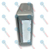
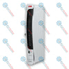
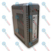
Bently Nevada 146031-01 3500/22M 10Base-T/100Base-TX I/O Module

SKU 146031-01

Disponibile
  • 12-month warranty
  • Free returns within 30 days
  • Manufacturer: Bently Nevada
  • Product No.: 146031-01
  • Origin United States
  • Product Type: Ethernet I/O Modules
  • Payment: T/T, Western Union
  • Weight: 0.2 kg
  • Dimensions: 24.4 mm x 241.3 mm x 99.1 mm (W x H x D)
  • Shipping port: Xiamen
  • Warranty: 12 months

Tags

Product Documentation

Technical Datasheet (PDF) Complete specifications and technical drawings.

Technical Datasheet

Bently Nevada 146031-01 3500/22M 10Base-T/100Base-TX I/O Module

Quantità

Product Description

Description

The Bently Nevada 146031-01 is a 10Base-T/100Base-TX Ethernet I/O Module designed for providing Ethernet interface connectivity and system contact interface functions for the 3500/22M Transient Data Interface (TDI) within the 3500 Machinery Monitoring System. Mounted in the rear slot directly behind the 3500/22M TDI main module, it features an RJ-45 Ethernet port supporting BN Host Protocol and BN TDI Protocol over TCP/IP to route steady-state and dynamic waveform data to host software such as System 1 Condition Monitoring and Diagnostic software. The 146031-01 incorporates an onboard OK Relay for rack status annunciation, system contact inputs for Trip Multiply, Alarm Inhibit, and Rack Reset, as well as a dedicated 2-pin Signal Common terminal for instrument ground connection.

Features

  • Autosensing 10Base-T or 100Base-TX Ethernet communication via RJ-45 connector
  • Integrated standard OK Relay rated for 5A @ 24 Vdc/120 Vac for rack fault annunciation
  • Built-in arc suppressors for relay contact protection
  • Terminal inputs for Trip Multiply, Alarm Inhibit, and Rack Reset dry contact system controls
  • Dedicated 2-pin connector for connecting Signal Common to single point Instrument Ground
  • Direct rear-slot interface for the 3500/22M Transient Data Interface (TDI) module

Applications

  • Bently Nevada 3500 Machinery Protection Systems
  • Ethernet communication and host software interfacing via System 1
  • Remote rack monitoring and transient waveform data acquisition
  • Critical machinery monitoring in power generation, oil and gas, and petrochemical facilities

Technical Specifications

Parameter Specification
Manufacturer Bently Nevada
Part Number 146031-01
Module Type 10Base-T/100Base-TX Ethernet I/O Module
Rack Space Requirement 1 full-height rear slot
Ethernet Communication 10Base-T or 100Base-TX Ethernet, autosensing (conforms to IEEE802.3)
Connector Type RJ-45 (telephone jack style)
Cable Length 100 metres (328 feet) maximum
Supported Protocols BN Host Protocol and BN TDI Protocol using Ethernet TCP/IP
OK Relay Function Indicates normal operation or rack faults; user-selectable OPEN or CLOSED contact (Normally Energized)
Standard OK Relay Rating 5A @ 24 Vdc / 120 Vac, 120 Watts / 600 VA Switched Power (maximum)
Arc Protection Integrated arc suppressors
Trip Multiply Input <1 mAdc, Dry Contact to Common
Alarm Inhibit Input <1 mAdc, Dry Contact to Common
Rack Reset Input <1 mAdc, Dry Contact to Common
Signal Common Connector 2-pin connector for single point Instrument Ground connection
Operating Temperature -30 degC to +65 degC (-22 degF to +149 degF)
Storage Temperature -40 degC to +85 degC (-40 degF to +185 degF)
Humidity 95%, non-condensing
Dimensions (H x W x D) 241.3 mm x 24.4 mm x 99.1 mm (9.50 in x 0.96 in x 3.90 in)
Weight 0.20 kg (0.44 lbs)

Installation Guidelines

  • Install the module into the single full-height rear slot directly behind the 3500/22M TDI main module.
  • Follow proper upgrade procedures when replacing a RIM I/O: remove RIM, remove RIM I/O, insert TDI I/O, and insert TDI to prevent module damage.
  • Connect standard Category 5 shielded Ethernet cable with RJ-45 connectors up to a maximum length of 100 metres (328 feet).
  • When connecting Signal Common to a single-point instrument ground using the 2-pin connector, slide the selector switch on the side of the Power Input Module (PIM) toward the "HP" arrow to isolate Signal Common from chassis ground.

Compliance and Certifications

  • EMC: European Community Directive 2014/30/EU; Standards: EN 61000-6-2, EN 61000-6-4
  • Electrical Safety: European Community Directive 2014/35/EU; Standard: EN 61010-1
  • RoHS: European Community Directive 2011/65/EU
  • FCC: Complies with part 15 of the FCC Rules
  • Maritime: DNV GL rules for classification; ABS Rules for Condition of Classification, Part 1
  • Hazardous Area Approvals: cNRTLus (Class I, Zone 2: AEx/Ex nA nC ic IIC T4 Gc / Class I, Zone 2: AEx/Ex ec nC ic IIC T4 Gc / Class I, Division 2, Groups A, B, C, D); ATEX/IECEx (II 3 G Ex nA nC ic IIC T4 Gc / Ex ec nC ic IIC T4 Gc)
Shipping &amp; Returns

Global Express Shipping

  • Standard Delivery: 4–6 business days via DHL, FedEx, and UPS.
  • Express Dispatch: Same-day dispatch for in-stock orders placed before 2:00 PM (GMT+8).
  • Worldwide Coverage: Serving over 150 countries.

Returns & Warranty

  • 30-Day Guarantee: Returns accepted for in-stock products in original, factory-sealed packaging.
  • 12-Month Warranty: Every industrial component is backed by our technical warranty.
FAQ
Which slot position does the I/O module occupy in the rack?
The module installs in the single full-height rear slot directly behind the 3500/22M TDI main module in Slot 1.
What Ethernet connector standard and maximum distance are supported by the interface?
The device features an RJ-45 connector for 10Base-T/100Base-TX Ethernet, supporting cable runs up to 100 meters.
How should Signal Common grounding be configured on the rear I/O board?
Connecting Signal Common to instrument ground via the 2-pin connector requires sliding the PIM switch toward HP.
Reviews

146031-01

Stock &amp; lead time on request

Call
1 su 1

Bently Nevada 146031-01 3500/22M 10Base-T/100Base-TX I/O Module

Only 5 item(s) left in stock
  • Manufacturer: Bently Nevada

  • Product No.: 146031-01

  • Country of origin:United States

  • Product Type: Ethernet I/O Modules

  • Payment: T/T, Western Union

  • Weight: 200g

  • Dimensions: 24.4 mm x 241.3 mm x 99.1 mm (W x H x D)

  • Shipping port: Xiamen

  • Warranty: 12 months

Quantità
Visualizza dettagli completi

Product Description

Description

The Bently Nevada 146031-01 is a 10Base-T/100Base-TX Ethernet I/O Module designed for providing Ethernet interface connectivity and system contact interface functions for the 3500/22M Transient Data Interface (TDI) within the 3500 Machinery Monitoring System. Mounted in the rear slot directly behind the 3500/22M TDI main module, it features an RJ-45 Ethernet port supporting BN Host Protocol and BN TDI Protocol over TCP/IP to route steady-state and dynamic waveform data to host software such as System 1 Condition Monitoring and Diagnostic software. The 146031-01 incorporates an onboard OK Relay for rack status annunciation, system contact inputs for Trip Multiply, Alarm Inhibit, and Rack Reset, as well as a dedicated 2-pin Signal Common terminal for instrument ground connection.

Features

  • Autosensing 10Base-T or 100Base-TX Ethernet communication via RJ-45 connector
  • Integrated standard OK Relay rated for 5A @ 24 Vdc/120 Vac for rack fault annunciation
  • Built-in arc suppressors for relay contact protection
  • Terminal inputs for Trip Multiply, Alarm Inhibit, and Rack Reset dry contact system controls
  • Dedicated 2-pin connector for connecting Signal Common to single point Instrument Ground
  • Direct rear-slot interface for the 3500/22M Transient Data Interface (TDI) module

Applications

  • Bently Nevada 3500 Machinery Protection Systems
  • Ethernet communication and host software interfacing via System 1
  • Remote rack monitoring and transient waveform data acquisition
  • Critical machinery monitoring in power generation, oil and gas, and petrochemical facilities

Technical Specifications

Parameter Specification
Manufacturer Bently Nevada
Part Number 146031-01
Module Type 10Base-T/100Base-TX Ethernet I/O Module
Rack Space Requirement 1 full-height rear slot
Ethernet Communication 10Base-T or 100Base-TX Ethernet, autosensing (conforms to IEEE802.3)
Connector Type RJ-45 (telephone jack style)
Cable Length 100 metres (328 feet) maximum
Supported Protocols BN Host Protocol and BN TDI Protocol using Ethernet TCP/IP
OK Relay Function Indicates normal operation or rack faults; user-selectable OPEN or CLOSED contact (Normally Energized)
Standard OK Relay Rating 5A @ 24 Vdc / 120 Vac, 120 Watts / 600 VA Switched Power (maximum)
Arc Protection Integrated arc suppressors
Trip Multiply Input <1 mAdc, Dry Contact to Common
Alarm Inhibit Input <1 mAdc, Dry Contact to Common
Rack Reset Input <1 mAdc, Dry Contact to Common
Signal Common Connector 2-pin connector for single point Instrument Ground connection
Operating Temperature -30 degC to +65 degC (-22 degF to +149 degF)
Storage Temperature -40 degC to +85 degC (-40 degF to +185 degF)
Humidity 95%, non-condensing
Dimensions (H x W x D) 241.3 mm x 24.4 mm x 99.1 mm (9.50 in x 0.96 in x 3.90 in)
Weight 0.20 kg (0.44 lbs)

Installation Guidelines

  • Install the module into the single full-height rear slot directly behind the 3500/22M TDI main module.
  • Follow proper upgrade procedures when replacing a RIM I/O: remove RIM, remove RIM I/O, insert TDI I/O, and insert TDI to prevent module damage.
  • Connect standard Category 5 shielded Ethernet cable with RJ-45 connectors up to a maximum length of 100 metres (328 feet).
  • When connecting Signal Common to a single-point instrument ground using the 2-pin connector, slide the selector switch on the side of the Power Input Module (PIM) toward the "HP" arrow to isolate Signal Common from chassis ground.

Compliance and Certifications

  • EMC: European Community Directive 2014/30/EU; Standards: EN 61000-6-2, EN 61000-6-4
  • Electrical Safety: European Community Directive 2014/35/EU; Standard: EN 61010-1
  • RoHS: European Community Directive 2011/65/EU
  • FCC: Complies with part 15 of the FCC Rules
  • Maritime: DNV GL rules for classification; ABS Rules for Condition of Classification, Part 1
  • Hazardous Area Approvals: cNRTLus (Class I, Zone 2: AEx/Ex nA nC ic IIC T4 Gc / Class I, Zone 2: AEx/Ex ec nC ic IIC T4 Gc / Class I, Division 2, Groups A, B, C, D); ATEX/IECEx (II 3 G Ex nA nC ic IIC T4 Gc / Ex ec nC ic IIC T4 Gc)

Product Documentation

Technical Datasheet (PDF) Complete specifications and technical drawings.

Technical Datasheet

Bently Nevada 146031-01 3500/22M 10Base-T/100Base-TX I/O Module

Which slot position does the I/O module occupy in the rack?

The module installs in the single full-height rear slot directly behind the 3500/22M TDI main module in Slot 1.

What Ethernet connector standard and maximum distance are supported by the interface?

The device features an RJ-45 connector for 10Base-T/100Base-TX Ethernet, supporting cable runs up to 100 meters.

How should Signal Common grounding be configured on the rear I/O board?

Connecting Signal Common to instrument ground via the 2-pin connector requires sliding the PIM switch toward HP.

Global Express Shipping

  • Standard Delivery: 4-6 Business Days via DHL, FedEx, and UPS.
  • Express Dispatch: Same-day dispatch for in-stock orders placed before 2:00 PM (GMT+8).
  • Worldwide Coverage: Serving over 150 countries, including rapid delivery to Saudi Arabia and UAE.

Returns & Warranty

  • 30-Day Guarantee: Returns accepted for in-stock products in original, factory-sealed packaging.
  • 12-Month Warranty: Every industrial component is backed by our professional technical warranty.

Orders are processed and delivered Monday-Friday (excluding public holidays).


For full eligibility, restocking fees, and international return details, please view our official Refund & Return Policy .

TECHNICAL SPECIFICATIONS

Color pattern
Greyish White
Country of origin
United States
Power source
DC Power

Technical knowledge

All'interno della CPU del PLC: cicli di scansione, memoria e selezione

Una guida pratica di ingegneria al funzionamento della CPU di un PLC, dai cicli di scansione deterministici e dalle tabelle delle immagini degli I/O fino a memoria, comunicazioni, diagnostica,...

Guida all’aggiornamento del firmware 1756-L73: scelta tra v19 e v21/v31

Sostituire un 1756-L73 non significa automaticamente aggiornare il firmware. Questa guida confronta le versioni 19.013, 21.011 e 31.011, concentrandosi sulla compatibilità dei progetti, sulle...

Implementazione della logica a scala XOR con 3 interruttori e bit interno

Implementa un circuito luminoso XOR con 3 interruttori SPST in LogixPro o RSLogix 500 utilizzando un bit di relè interno. Include tabelle della verità, equazioni booleane e verifica.

Creazione di una rete Modbus RTU con CompactLogix e DeltaV

Integra Allen-Bradley CompactLogix, Caterpillar ATS e generatori nel DCS DeltaV tramite Modbus RTU. Include i gateway ProSoft MVI69-MCM e Miille DIN266.

Istruzione ONS che non attiva l’OTE nella logica ladder di Studio 5000

L’istruzione ONS si attiva, ma la bobina OTE non rimane mai eccitata in Studio 5000 perché il one-shot è vero solo per una scansione. Usa OTL/OTU oppure una logica di autoritenuta.

Requisiti e topologia dello switch di rete EtherNet/IP Kinetix 5500

Configura i servoazionamenti Allen-Bradley Kinetix 5500 su EtherNet/IP. Include CIP Sync, la temporizzazione IEEE 1588 V2, la selezione degli switch Stratix, la topologia DLR e l’HMI.