Description
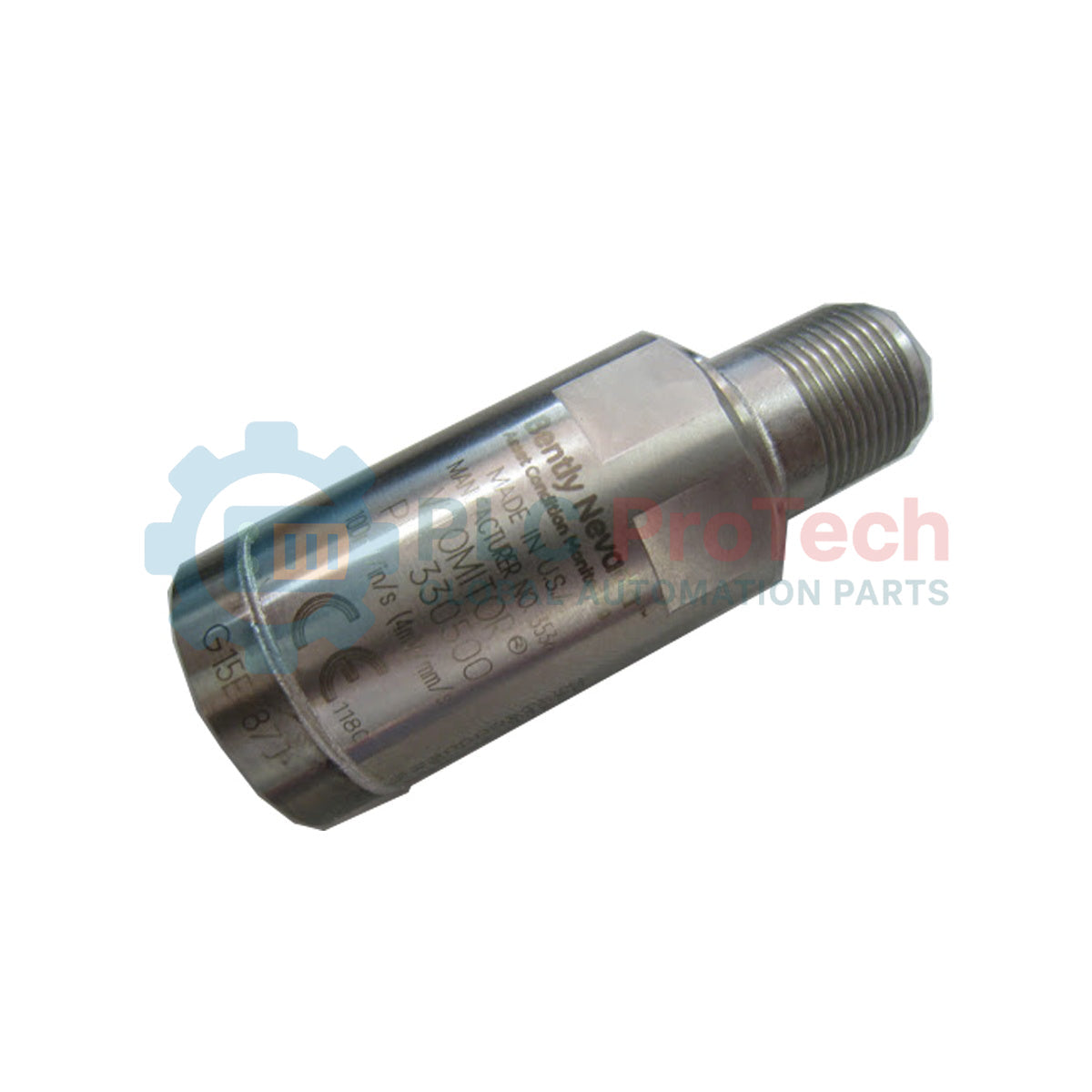
Measuring casing vibration velocity directly on rotating machinery, the Bently Nevada 330500-03-CN integrates a rugged piezoelectric accelerometer with an internal integration circuit to output a true velocity signal. This design eliminates the requirement for external signal integration at the monitoring system, providing a robust and less noise-susceptible velocity output directly from the sensor casing. The device is housed in hermetically sealed stainless steel, engineered specifically to withstand severe, high-humidity industrial environments. Standard implementation incorporates a 1/4-28 UNF mounting thread and country-specific agency certifications, ensuring compliance with local plant safety standards.
Features
-
Piezoelectric Sensing Element: Incorporates a solid-state internal integrator to output a clean velocity waveform rather than raw acceleration.
-
Hermetic Seal: Complete 316L stainless steel enclosure prevents ingress of moisture, oils, and chemical contaminants.
-
Two-Pin Mil-C-5015 Connector: Top-exit standard industrial connection interface minimizes installation footprint.
-
Electrostatic Shielding: Internal Faraday shield isolates the sensing circuitry from electrostatic interference and electromagnetic fields.
Applications
- Casing vibration measurements on steam and gas turbine bearings.
- Real-time casing velocity monitoring on balance-of-plant machinery including pumps, draft fans, and air compressors.
- Industrial gearbox casing diagnostic monitoring.
- Paper machine dryer roll bearings and harsh wet-end industrial processing zones.
Technical Specifications Table
| Parameter |
Specification Value |
| Manufacturer |
Bently Nevada |
| Model Number |
330500-03-CN |
| Sensor Type |
Piezo-velocity (Velomitor) |
| Mounting Thread Option |
1/4 - 28 UNF (Option 03) |
| Agency Approval |
CN (Country-specific hazardous area certifications) |
| Connection Interface |
2-pin MIL-C-5015 receptacle |
| Casing Material |
Stainless Steel |
| Operating Bias Voltage |
Nominally -12 VDC (relative to common) |
| Net Weight |
0.142 kg (0.31 lbs) |
| Shipping Weight (Calculated) |
1.50 kg (3.30 lbs) |
| Country of Origin |
United States (U.S.A.) |
Connections and Interfaces
| Connector Pin |
Function / Circuit Assignment |
| Pin A |
Signal / Power (Bias and dynamic AC velocity signal) |
| Pin B |
Signal Return / Common |
| Shield / Shell |
Case ground (electrically isolated from internal signal pins) |
Empirical Engineering Insights
Alternative Models & Compatibility
The 330500-03-CN is drop-in backward compatible with older Bently Nevada velocity transducers requiring standard 1/4-28 UNF casing mounting. Always verify monitor channel configuration; when replacing older electro-mechanical velocity sensors (like the 9200 series) with the 330500 piezo-velocity sensor, you must switch the monitor card jumper or software settings from "Seismic" (self-generating) to "Velomitor" (powered -24 VDC constant current) to prevent a transducer OK limit fault.
Application Pitfalls & Engineering Notes
Because the Velomitor utilizes an internal piezoelectric design, rapid ambient temperature variations can induce a transient thermal shock. This thermal expansion or contraction of the crystal mimics low-frequency vibration, triggering spurious "High Velocity" alarms. Avoid mounting the sensor directly opposite uninsulated steam pipe flanges, steam leaks, or cooling vents. If thermal transients are unavoidable, install a heat-insulating boot over the sensor body.
Commissioning & Wiring Tips
Always utilize 2-conductor shielded twisted-pair cabling (such as Bently Nevada 9571) for the signal run. To eliminate ground loops, terminate the cable shield only at the monitoring system / cabinet terminal strip. Cut the shield flush and insulate it with heat-shrink at the sensor's MIL connector end. Ensure the sensor mounting surface is machined flat to a surface finish of 0.8 micrometers (32 microinches) Ra to guarantee precise high-frequency mechanical transmission.
Installation Guidelines
CRITICAL WARNING:
Prior to starting the installation, ensure the target machinery is completely shut down, isolated, and locked out/tagged out (LOTO). Do not exceed the maximum mounting torque specification of 4.5 Nm (40 in-lb). Over-torqueing can cause permanent damage to the internal piezoelectric crystal assembly or strip the 1/4-28 thread adapter.
1
Prepare Mounting Spot: Drill and tap a perpendicular hole to a depth of at least 6 mm (0.25 inches) using the 1/4-28 UNF specification. Spot-face the surface to ensure complete, flat contact.
2
Apply Coupling Compound: Spread a thin, uniform layer of silicone grease or acoustic coupling fluid on the mating surface to optimize mechanical energy transfer.
3
Torque the Sensor: Thread the sensor into the mounting adapter and tighten using a calibrated torque wrench. Apply exactly 4.5 Nm (40 in-lb) of torque.
4
Connect & Secure Cable: Attach the MIL-C-5015 cable connector. Provide a drip loop in the cable immediately exiting the sensor, and secure the conduit or cable armor to the machine housing to prevent whipping or cable-induced strain.