Bently Nevada

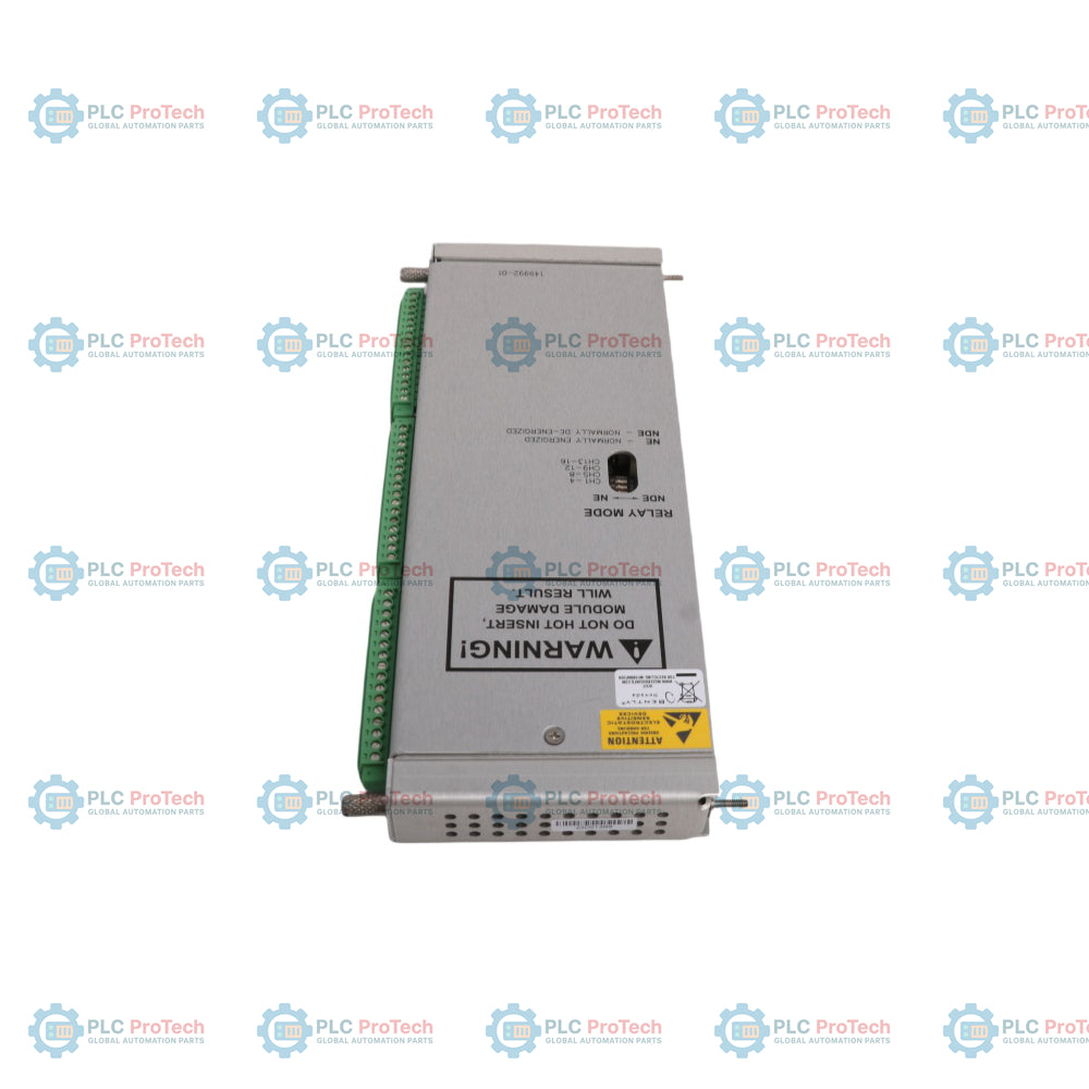
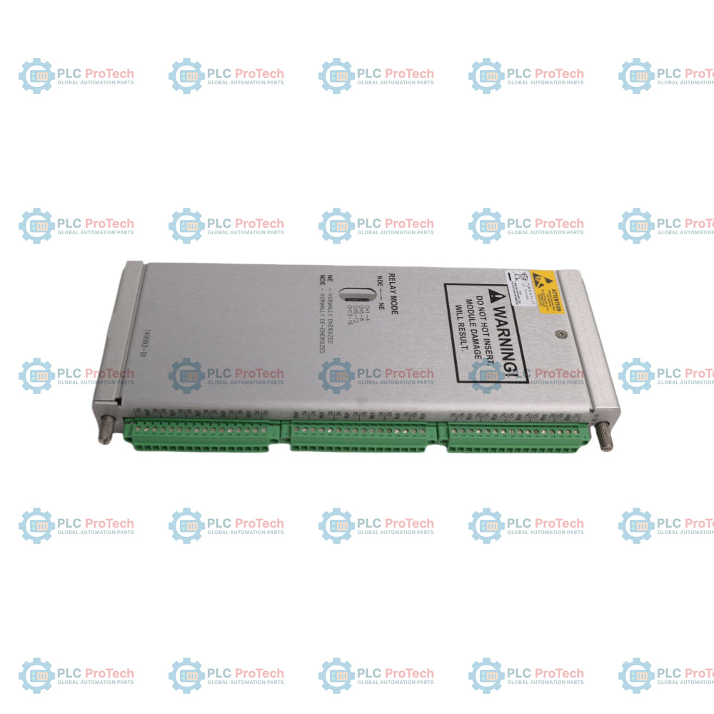
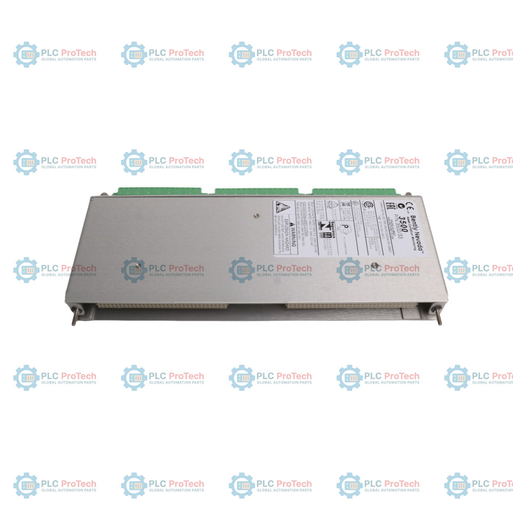
Bently Nevada 3500/33-03-00 149992-03 Low Current 16-Channel Relay Output Module

SKU 3500/33-03-00 149992-03

Disponibile
  • 12-month warranty
  • Free returns within 30 days
  • Manufacturer: Bently Nevada
  • Product No.: 3500/33-03-00 149992-03
  • Origin United States
  • Product Type: Relay Output Module
  • Barcode: 8537101190
  • Payment: T/T, Western Union
  • Weight: 1.23 kg
  • Dimensions: 241.3 mm x 24.4 mm x 241.8 mm
  • Shipping port: Xiamen
  • Warranty: 12 months

Tags

Product Documentation

Technical Datasheet (PDF) Complete specifications and technical drawings.

Technical Datasheet

Bently Nevada 3500/33-03-00 149992-03 Low Current 16-Channel Relay Output Module

Quantità

Product Description

Description

The Bently Nevada 3500/33-03-00 149992-03 is a full-height 16-channel relay output module designed to provide advanced programmable safety voting and alarm drive logic for the 3500 Series Machinery Protection System. As a factory-configured low-current assembly, the 3500/33-03-00 149992-03 features specialized gold-plated relay contacts engineered specifically to ensure maximum contact integrity and prevent surface oxidation in low-power signaling applications. Each of its sixteen independent outputs possesses dedicated Alarm Drive Logic, allowing operators to program complex combinational AND/OR logic gates utilizing alert, danger, or Not-OK statuses gathered from any vibration, position, or temperature monitor module across the rack. This combined hardware and software solution serves as a highly reliable, hardware-voted emergency trip bridge between critical plant rotating assets and external Distributed Control Systems (DCS), programmable logic controllers (PLC), or Emergency Shutdown Systems (ESD).

Features

  • Complete integrated 16-channel safety relay assembly consisting of the 3500/33-03-00 system code and the 149992-03 gold-contact main processor board.
  • Onboard gold-plated contacts optimized for highly stable low-voltage and low-current circuit switching.
  • Highly flexible Alarm Drive Logic matrix supporting customized voting schemes based on multi-channel alert and danger variables.
  • Live-swap hot-pluggable architecture enabling seamless physical card replacement without disturbing adjacent online machinery protection loops.
  • Individual hardware switch assignments on the circuit board allowing independent Normally Energized (NE) or Normally De-energized (NDE) configuration per relay.
  • Clear front-panel LED diagnostics providing real-time visual assessment of module health (OK), backplane communication bus activity (TX/RX), and individual channel alarm states.

Applications

  • Low-current alarm link interfaces connecting heavy rotating machinery protection racks to industrial PLCs and safety controllers.
  • Distributed logic voting and automated emergency shutdown mapping for high-criticality steam turbines, gas turbines, and compressors.
  • Multi-point protective trip signaling inside demanding petrochemical facilities, oil refineries, and power generation stations.

Ordering Information

Ordering Code / Component Part Number Description
3500/33-03-00 16-Channel Relay Module complete assembly with Low Current Relays, No Agency Approvals.
A: 03 Low Current Relay Module option (utilizes Output Module with Gold Contacts).
B: 00 Agency Approval Option: None.
149992-03 Main Board Component: Low Current 16-Channel Relay Main Module with Gold-Plated Contacts.

Technical Specifications

Parameter Category Specification Details
Manufacturer Bently Nevada (Baker Hughes)
Combined Designation 3500/33-03-00 149992-03
Module Type 16-Channel Relay Module (Low Current Gold Variant)
Power Consumption 5.8 Watts typical
Relay Contact Type Single-pole, double-throw (SPDT) / Gold-plated contacts
Minimum Contact Load 1 V, 1 mA minimum
Maximum Contact Load 30 Vdc at 2 A resistive / 48 Vdc at 0.2 A resistive / 125 Vdc at 0.1 A resistive / 250 Vac at 2 A resistive
Contact Operation Mode Onboard switch-selectable for Normally De-energized (NDE) or Normally Energized (NE)
Operating Temperature -30 degC to +65 degC (-22 degF to +150 degF)
Storage Temperature -40 degC to +85 degC (-40 degF to +185 degF)
Relative Humidity 95%, non-condensing
Main Card Dimensions 241.3 mm x 24.4 mm x 241.8 mm (9.50 in x 0.96 in x 9.52 in)
I/O Card Dimensions 241.3 mm x 24.4 mm x 99.1 mm (9.50 in x 0.96 in x 3.90 in)
Main Module Weight 0.82 kg (1.8 lb)
I/O Module Weight 0.41 kg (0.9 lb)

Connections/Interfaces

The diagnostic readouts on the front and the physical terminations on the rear facilitate distinct interface tracking:

Component Identifier Functional Description / Assignment
OK LED Front panel health light; remains solid green when internal software algorithms process normally.
TX/RX LED Front panel communication light; flashes rapidly to indicate active digital backplane traffic.
CHALRM LEDs (1 - 16) Channel status lights; independent LEDs illuminate directly to show when a specific relay channel is tripped.
Rear Terminal Block Contacts I/O backplane connection pins grouping Common (COM), Normally Open (NO), and Normally Closed (NC) lines.
Relay Mode Toggles Physical multi-position dual-throw onboard switches assigning individual channel states to NDE or NE.

Installation Guidelines

  • Rack Positioning: Slide the complete 3500/33-03-00 149992-03 module assembly into any available full-height slot located strictly to the right of the Transient Data Interface (TDI) module.
  • Rear Alignment: Secure the corresponding 16-channel internal termination input/output module (such as 149986-01) into the matching rear slot directly behind the main card.
  • Onboard Switch Configuration: Adjust the internal physical toggle switches to determine the required Normally Energized or Normally De-energized status for each channel before sliding the board into the live slot.
  • Loop Voltage Verification: Confirm that the downstream instrumentation loops comply strictly with low-voltage and low-current constraints; introducing heavy inductive or high-power loads will destroy the gold-plated contact surfaces.
  • Logic Deployment: Open the system rack software suite to map and download the intended AND/OR safety voting matrix into the module non-volatile memory prior to system testing.

Compliance and Certifications

  • EMC Directives: European Community Directive 2014/30/EU (EMC Directive).
  • EMC Standards: EN 61000-6-2 (Industrial Immunity), EN 61000-6-4 (Industrial Emissions).
  • Electrical Safety: Low Voltage Directive 2014/35/EU, EN 61010-1 Standard.
  • RoHS Directive: 2011/65/EU European Compliance.
  • Hazardous Area Approvals: cNRTLus Class I, Zone 2: AEx/Ex nA nC ic IIC T4 Gc / Class I, Division 2, Groups A, B, C, and D (T4 @ Ta = -20 degC to +65 degC).
  • ATEX/IECEx Approvals: II 3 G Ex nA nC ic IIC T4 Gc / Ex ec nC ic IIC T4 Gc.

FAQ

What is the functional relationship between the 3500/33-03-00 code and the 149992-03 part number?

The 3500/33-03-00 represents the complete factory ordering model number specifying a 16-channel relay system configured for low-current applications, while the 149992-03 is the exact manufacturer part number printed on the physical low-current main processor board included in that specific combination.

Why is gold plating critical for the contacts on this module?

Gold plating is vital for low-current circuitry (down to 1 V, 1 mA) because standard silver contacts develop surface oxidation layers over time under low electrical loads, whereas gold resists tarnish to guarantee a clean connection path.

Can I perform a hot-swap on this module while machinery monitoring is actively running?

Yes, the unit features a fully hot-swappable architecture, allowing maintenance teams to remove or insert the card into the slot without disconnecting power or causing signal drops on adjacent monitor channels.

Does a single order of this product supply both the front processor and the rear terminal board?

When purchased as a complete surplus or spare assembly assembly under these factory specifications, it typically denotes the main card; ensure you verify whether your specific system panel requires the matching 149986-01 rear internal termination block as well.

Shipping & Returns

Global Express Shipping

  • Standard Delivery: 4–6 business days via DHL, FedEx, and UPS.
  • Express Dispatch: Same-day dispatch for in-stock orders placed before 2:00 PM (GMT+8).
  • Worldwide Coverage: Serving over 150 countries.

Returns & Warranty

  • 30-Day Guarantee: Returns accepted for in-stock products in original, factory-sealed packaging.
  • 12-Month Warranty: Every industrial component is backed by our technical warranty.
Reviews

3500/33-03-00 149992-03

Stock & lead time on request

Call
1 su 3

Bently Nevada 3500/33-03-00 149992-03 Low Current 16-Channel Relay Output Module

Only 7 item(s) left in stock
  • Manufacturer: Bently Nevada

  • Product No.: 3500/33-03-00 149992-03

  • Country of origin:United States

  • Product Type: Relay Output Module

  • Barcode: 8537101190

  • Payment: T/T, Western Union

  • Weight: 1230g

  • Dimensions: 241.3 mm x 24.4 mm x 241.8 mm

  • Shipping port: Xiamen

  • Warranty: 12 months

Quantità
Visualizza dettagli completi

Product Description

Description

The Bently Nevada 3500/33-03-00 149992-03 is a full-height 16-channel relay output module designed to provide advanced programmable safety voting and alarm drive logic for the 3500 Series Machinery Protection System. As a factory-configured low-current assembly, the 3500/33-03-00 149992-03 features specialized gold-plated relay contacts engineered specifically to ensure maximum contact integrity and prevent surface oxidation in low-power signaling applications. Each of its sixteen independent outputs possesses dedicated Alarm Drive Logic, allowing operators to program complex combinational AND/OR logic gates utilizing alert, danger, or Not-OK statuses gathered from any vibration, position, or temperature monitor module across the rack. This combined hardware and software solution serves as a highly reliable, hardware-voted emergency trip bridge between critical plant rotating assets and external Distributed Control Systems (DCS), programmable logic controllers (PLC), or Emergency Shutdown Systems (ESD).

Features

  • Complete integrated 16-channel safety relay assembly consisting of the 3500/33-03-00 system code and the 149992-03 gold-contact main processor board.
  • Onboard gold-plated contacts optimized for highly stable low-voltage and low-current circuit switching.
  • Highly flexible Alarm Drive Logic matrix supporting customized voting schemes based on multi-channel alert and danger variables.
  • Live-swap hot-pluggable architecture enabling seamless physical card replacement without disturbing adjacent online machinery protection loops.
  • Individual hardware switch assignments on the circuit board allowing independent Normally Energized (NE) or Normally De-energized (NDE) configuration per relay.
  • Clear front-panel LED diagnostics providing real-time visual assessment of module health (OK), backplane communication bus activity (TX/RX), and individual channel alarm states.

Applications

  • Low-current alarm link interfaces connecting heavy rotating machinery protection racks to industrial PLCs and safety controllers.
  • Distributed logic voting and automated emergency shutdown mapping for high-criticality steam turbines, gas turbines, and compressors.
  • Multi-point protective trip signaling inside demanding petrochemical facilities, oil refineries, and power generation stations.

Ordering Information

Ordering Code / Component Part Number Description
3500/33-03-00 16-Channel Relay Module complete assembly with Low Current Relays, No Agency Approvals.
A: 03 Low Current Relay Module option (utilizes Output Module with Gold Contacts).
B: 00 Agency Approval Option: None.
149992-03 Main Board Component: Low Current 16-Channel Relay Main Module with Gold-Plated Contacts.

Technical Specifications

Parameter Category Specification Details
Manufacturer Bently Nevada (Baker Hughes)
Combined Designation 3500/33-03-00 149992-03
Module Type 16-Channel Relay Module (Low Current Gold Variant)
Power Consumption 5.8 Watts typical
Relay Contact Type Single-pole, double-throw (SPDT) / Gold-plated contacts
Minimum Contact Load 1 V, 1 mA minimum
Maximum Contact Load 30 Vdc at 2 A resistive / 48 Vdc at 0.2 A resistive / 125 Vdc at 0.1 A resistive / 250 Vac at 2 A resistive
Contact Operation Mode Onboard switch-selectable for Normally De-energized (NDE) or Normally Energized (NE)
Operating Temperature -30 degC to +65 degC (-22 degF to +150 degF)
Storage Temperature -40 degC to +85 degC (-40 degF to +185 degF)
Relative Humidity 95%, non-condensing
Main Card Dimensions 241.3 mm x 24.4 mm x 241.8 mm (9.50 in x 0.96 in x 9.52 in)
I/O Card Dimensions 241.3 mm x 24.4 mm x 99.1 mm (9.50 in x 0.96 in x 3.90 in)
Main Module Weight 0.82 kg (1.8 lb)
I/O Module Weight 0.41 kg (0.9 lb)

Connections/Interfaces

The diagnostic readouts on the front and the physical terminations on the rear facilitate distinct interface tracking:

Component Identifier Functional Description / Assignment
OK LED Front panel health light; remains solid green when internal software algorithms process normally.
TX/RX LED Front panel communication light; flashes rapidly to indicate active digital backplane traffic.
CHALRM LEDs (1 - 16) Channel status lights; independent LEDs illuminate directly to show when a specific relay channel is tripped.
Rear Terminal Block Contacts I/O backplane connection pins grouping Common (COM), Normally Open (NO), and Normally Closed (NC) lines.
Relay Mode Toggles Physical multi-position dual-throw onboard switches assigning individual channel states to NDE or NE.

Installation Guidelines

  • Rack Positioning: Slide the complete 3500/33-03-00 149992-03 module assembly into any available full-height slot located strictly to the right of the Transient Data Interface (TDI) module.
  • Rear Alignment: Secure the corresponding 16-channel internal termination input/output module (such as 149986-01) into the matching rear slot directly behind the main card.
  • Onboard Switch Configuration: Adjust the internal physical toggle switches to determine the required Normally Energized or Normally De-energized status for each channel before sliding the board into the live slot.
  • Loop Voltage Verification: Confirm that the downstream instrumentation loops comply strictly with low-voltage and low-current constraints; introducing heavy inductive or high-power loads will destroy the gold-plated contact surfaces.
  • Logic Deployment: Open the system rack software suite to map and download the intended AND/OR safety voting matrix into the module non-volatile memory prior to system testing.

Compliance and Certifications

  • EMC Directives: European Community Directive 2014/30/EU (EMC Directive).
  • EMC Standards: EN 61000-6-2 (Industrial Immunity), EN 61000-6-4 (Industrial Emissions).
  • Electrical Safety: Low Voltage Directive 2014/35/EU, EN 61010-1 Standard.
  • RoHS Directive: 2011/65/EU European Compliance.
  • Hazardous Area Approvals: cNRTLus Class I, Zone 2: AEx/Ex nA nC ic IIC T4 Gc / Class I, Division 2, Groups A, B, C, and D (T4 @ Ta = -20 degC to +65 degC).
  • ATEX/IECEx Approvals: II 3 G Ex nA nC ic IIC T4 Gc / Ex ec nC ic IIC T4 Gc.

FAQ

What is the functional relationship between the 3500/33-03-00 code and the 149992-03 part number?

The 3500/33-03-00 represents the complete factory ordering model number specifying a 16-channel relay system configured for low-current applications, while the 149992-03 is the exact manufacturer part number printed on the physical low-current main processor board included in that specific combination.

Why is gold plating critical for the contacts on this module?

Gold plating is vital for low-current circuitry (down to 1 V, 1 mA) because standard silver contacts develop surface oxidation layers over time under low electrical loads, whereas gold resists tarnish to guarantee a clean connection path.

Can I perform a hot-swap on this module while machinery monitoring is actively running?

Yes, the unit features a fully hot-swappable architecture, allowing maintenance teams to remove or insert the card into the slot without disconnecting power or causing signal drops on adjacent monitor channels.

Does a single order of this product supply both the front processor and the rear terminal board?

When purchased as a complete surplus or spare assembly assembly under these factory specifications, it typically denotes the main card; ensure you verify whether your specific system panel requires the matching 149986-01 rear internal termination block as well.

Product Documentation

Technical Datasheet (PDF) Complete specifications and technical drawings.

Technical Datasheet

Bently Nevada 3500/33-03-00 149992-03 Low Current 16-Channel Relay Output Module

Global Express Shipping

  • Standard Delivery: 4-6 Business Days via DHL, FedEx, and UPS.
  • Express Dispatch: Same-day dispatch for in-stock orders placed before 2:00 PM (GMT+8).
  • Worldwide Coverage: Serving over 150 countries, including rapid delivery to Saudi Arabia and UAE.

Returns & Warranty

  • 30-Day Guarantee: Returns accepted for in-stock products in original, factory-sealed packaging.
  • 12-Month Warranty: Every industrial component is backed by our professional technical warranty.

Orders are processed and delivered Monday-Friday (excluding public holidays).


For full eligibility, restocking fees, and international return details, please view our official Refund & Return Policy .

TECHNICAL SPECIFICATIONS

Color pattern
Silver
Country of origin
United States
Power source
DC Power

Technical knowledge

1756-L73 Firmware Upgrade Guide: v19 vs v21/v31 Decision

Replacing a 1756-L73 does not automatically mean upgrading its firmware. This guide compares v19.013, v21.011 and v31.011, focusing on project compatibility, HMI communications, legacy networks and...

Implementing 3-Switch XOR Ladder Logic with Internal Bit

Implement a 3-SPST switch XOR light circuit in LogixPro or RSLogix 500 using an internal relay bit. Includes truth tables, boolean equations, and verified.

Building a Modbus RTU Network with CompactLogix and DeltaV

Integrate Allen-Bradley CompactLogix, Caterpillar ATS, and generators into DeltaV DCS over Modbus RTU. Covers ProSoft MVI69-MCM, Miille DIN266 gateways.

ONS Instruction Not Energizing OTE in Studio 5000 Ladder Logic

ONS instruction fires but the OTE coil never latches in Studio 5000 because the one-shot is only true for one scan. Use OTL/OTU or seal-in logic instead.

Kinetix 5500 EtherNet/IP Network Switch Requirements and Topology

Configure Allen-Bradley Kinetix 5500 servo drives on EtherNet/IP. Covers CIP Sync, IEEE 1588 V2 timing, Stratix selection, DLR topology, and HMI.

Moving Average Filtering in DCS and PLC Analog Control

A moving-average filter is the sliding-window smoother most instrument engineers drop into DCS and PLC analog paths. Here is how the window works, how N and sample time set lag, and when a...