HIMA

HIMA F30 01 HIMatrix Compact Safety Controller

SKU F30 01

Disponibile
  • 12-month warranty
  • Free returns within 30 days
  • Manufacturer: HIMA
  • Product No.: F30 01
  • Origin Germany
  • Product Type: Safety Controller Module
  • Barcode: 8537101190
  • Payment: T/T, Western Union
  • Weight: 1.2 kg
  • Dimensions: 114 mm x 257 mm x 66 mm (H x W x D)
  • Shipping port: Xiamen
  • Warranty: 12 months

Tags

Product Documentation

Technical Datasheet (PDF) Complete specifications and technical drawings.

Technical Datasheet

HIMA F30 01 HIMatrix Compact Safety Controller

Quantità

Product Description

Description

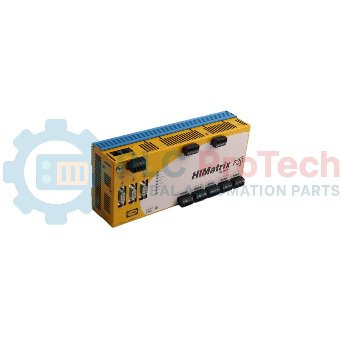
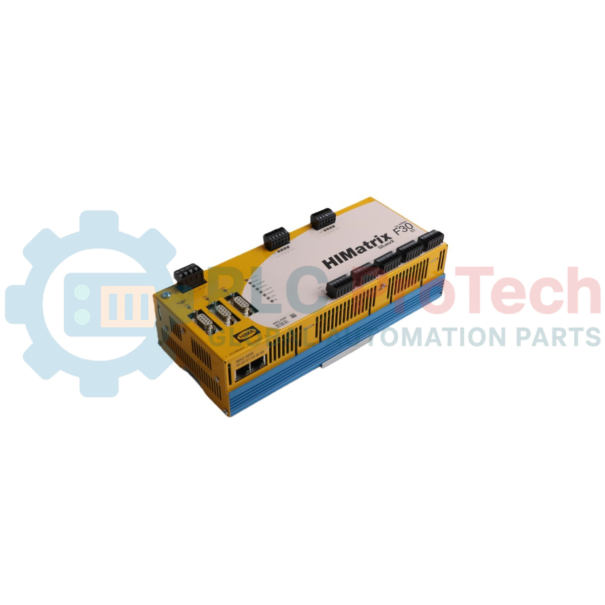
The HIMA F30 01 is a safety-related compact controller housed in a metal enclosure designed for safety-critical automation applications. Equipped with 20 safety-related digital inputs and 8 safety-related digital outputs, the F30 01 processes process logic under the de-energized-to-trip safety principle. The controller features four RJ-45 Ethernet ports with an integrated switch supporting safeethernet communication, as well as three 9-pole D-sub serial fieldbus interfaces for flexible industrial network integration. Engineered for high-reliability systems, the F30 01 is suitable for deployment in safety instrumented systems (SIS) and hazardous locations classified as Zone 2.

Features

  • Integrated I/O Capacity: Includes 20 non-galvanically isolated safety-related digital inputs and 8 non-galvanically isolated safety-related digital outputs.
  • Ethernet Communication: Features 4 x RJ-45 10/100Base-T ports with auto-negotiation, auto-crossover, and integrated switch supporting safeethernet, Modbus TCP, OPC, and SNTP.
  • Fieldbus Versatility: Submodule slots (FB1, FB2) and dedicated RS485 interface (FB3) support PROFIBUS DP Master/Slave, Modbus Master/Slave, RS232/RS422 ComUserTask, and INTERBUS Master.
  • Line Control Functionality: Supports short-circuit and open-circuit detection on digital input lines when pulsed outputs are routed through monitored contacts.
  • Status Diagnostics: LED indicators on the front panel provide real-time status for 24 VDC supply, system states (RUN, ERROR, PROG, FORCE, FAULT, OSL, BL), Ethernet links, and channel I/Os.
  • Hardware Clock Buffering: Integrated gold capacitor buffers the internal hardware clock for approximately one week during power interruption.

Applications

  • Safety Instrumented Systems (SIS)
  • Emergency Shutdown (ESD) systems
  • Burner Management Systems (BMS)
  • Fire and Gas (F&G) detection systems
  • Process control safety loops requiring up to SIL 3 architecture

Ordering Information

Designation Description Part No.
F30 01 Compact controller with 20 digital inputs and 8 digital outputs. Operating temperature 0 degC to +60 degC, for ELOP II Factory programming tool 98 2200415
F30 011 (-20 degC) Compact controller with 20 digital inputs and 8 digital outputs. Operating temperature -20 degC to +60 degC, for ELOP II Factory programming tool 98 2200455
F30 01 SILworX Compact controller with 20 digital inputs and 8 digital outputs. Operating temperature 0 degC to +60 degC, for SILworX programming tool 98 2200472
F30 011 SILworX (-20 degC) Compact controller with 20 digital inputs and 8 digital outputs. Operating temperature -20 degC to +60 degC, for SILworX programming tool 98 2200478

Technical Specifications

Category Parameter Specification
General Manufacturer HIMA Paul Hildebrandt GmbH + Co KG
  Country of Origin Germany
  Dimensions 114 mm x 257 mm x 66 mm (H x W x D with fixing bolt/screws)
  Weight approx. 1.2 kg
Electrical Operating Voltage 24 VDC (-15%...+20%, Wss <= 15%) from SELV/PELV power supply unit
  Current Input Max. 8 A (with maximum load); Idle: 0.5 A
  External Fuse 10 A time-lag (T)
  Response Time >= 20 ms
Environmental Operating Temperature 0 degC to +60 degC (F30 01 standard); -20 degC to +60 degC (F30 011 model)
  Storage Temperature -40 degC to +85 degC
  Protection Class Protection class III in accordance with IEC/EN 61131-2
  Protection Type IP20
  Pollution Degree Pollution degree II in accordance with IEC/EN 61131-2
  Altitude < 2000 m
Digital Inputs Quantity 20 (non-galvanically isolated)
  High Level Voltage: 15...30 VDC; Current: >= 2 mA at 15 V
  Low Level Voltage: max. 5 VDC; Current: max. 1.5 mA (1 mA at 5 V)
  Switching Point typ. 7.5 V
  Sensor Supply 5 x 20 V / 100 mA (at 24 V), short-circuit-proof
Digital Outputs Quantity 8 (non-galvanically isolated)
  Output Voltage >= L+ minus 2 V
  Output Current Channels 1...3 & 5...7: 0.5 A at 60 degC; Channels 4 & 8: 1 A at 60 degC, 2 A at 50 degC
  Minimum Load 2 mA for each channel
  Internal Voltage Drop max. 2 V at 2 A
  Leakage Current max. 1 mA at 2 V (low level)
Communication Ethernet Ports 4 x RJ-45, 10/100Base-T (with 100 Mbit/s) with integrated switch
  Fieldbus Interfaces FB1, FB2 (9-pole D-sub, optional submodules); FB3 (9-pole D-sub RS485)

Connections/Interfaces

D-sub FB1 / FB2 Interface Options

Connector Pin PROFIBUS DP Signal RS485 Signal RS232 Signal RS422 Signal INTERBUS Signal
1 - - - - DO
2 - RP (+5 V) TxD RP (+5 V) DI
3 RxD/TxD-A RxD/TxD-A RxD RxA COM
4 RTS CNTR-A - TxA -
5 DGND DGND DGND DGND -
6 VP (+5 V) VP (+5 V) - VP (+5 V) DO-
7 - - RTS - DI-
8 RxD/TxD-B RxD/TxD-B - RxB -
9 - CNTR-B - TxB -

D-sub FB3 Interface (Modbus / RS485)

Connector Pin Function
3 RxD/TxD-A (Receive/send data A)
4 CNTR-A (Control signal A)
5 DGND (Data ground)
6 VP (+5 V supply voltage)
8 RxD/TxD-B (Receive/send data B)
9 CNTR-B (Control signal B)

Input Terminal Assignments

Terminal Designation Function
13, 19, 25, 31, 37 LS+ Sensor supply (for input groups 1..4, 5..8, 9..12, 13..16, 17..20)
14, 15, 16, 17 1, 2, 3, 4 Digital inputs 1 to 4
20, 21, 22, 23 5, 6, 7, 8 Digital inputs 5 to 8
26, 27, 28, 29 9, 10, 11, 12 Digital inputs 9 to 12
32, 33, 34, 35 13, 14, 15, 16 Digital inputs 13 to 16
38, 39, 40, 41 17, 18, 19, 20 Digital inputs 17 to 20
18, 24, 30, 36, 42 L- Ground

Output Terminal Assignments

Terminal Designation Function
1, 7 LS+ Sensor supply / power supply connection
2, 3, 4, 5 1, 2, 3, 4 Digital outputs 1, 2, 3 (0.5 A) and 4 (1 A / 2 A)
8, 9, 10, 11 5, 6, 7, 8 Digital outputs 5, 6, 7 (0.5 A) and 8 (1 A / 2 A)
6, 12 L- Ground channel group

Installation Guidelines

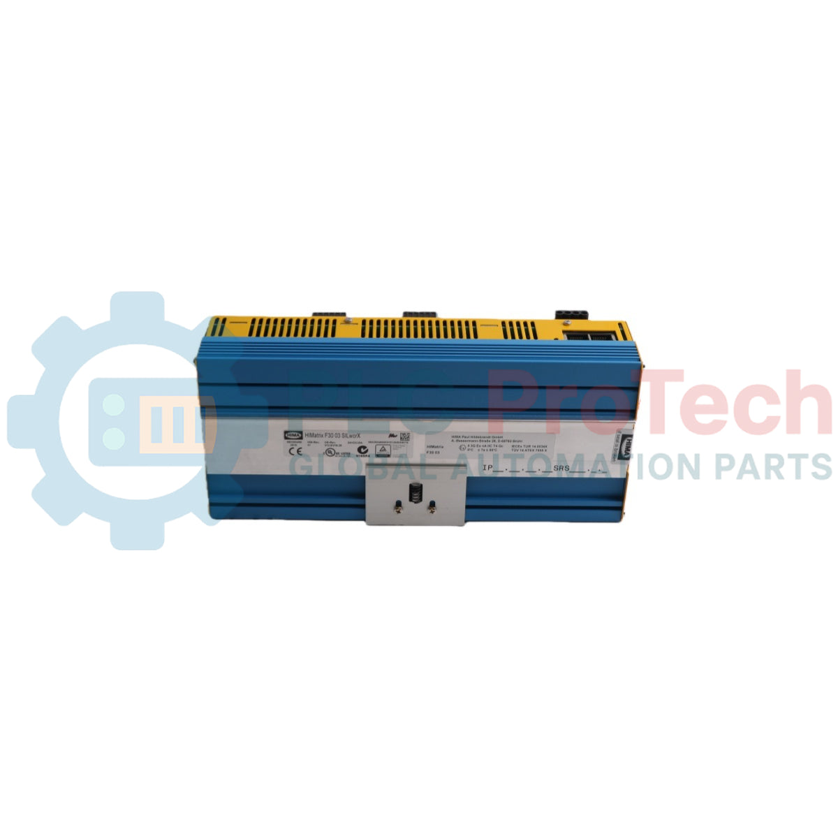
  • DIN Rail Mounting: Mount the controller on a 35 mm DIN rail inside a standard industrial enclosure.
  • Overcurrent Protection: Install a 10 A time-lag fuse on the power supply side to protect the internal circuitry.
  • Power Supply: Power the unit using a 24 VDC source with protective extra-low voltage (PELV) or safety extra-low voltage (SELV) safe isolation.
  • Hazardous Area (Zone 2) Mounting: When installing in Zone 2, house the controller in an enclosure meeting EN 60079-15 with at least IP54 protection in accordance with EN 60529. Ensure the enclosure dissipates the device heat output (12 W to 33 W depending on load).
  • Grounding and Actuators: Connect load devices using the designated L- ground terminal of the corresponding output group to ensure built-in protection circuits operate correctly.
  • Surge Mitigation: In environment conditions subject to surges (EN 61000-4-5), use shielded input wiring and enable software noise blanking.

Compliance and Certifications

  • CE: EMC, ATEX Zone 2
  • TUV Safety: IEC 61508 1-7:2000 up to SIL 3, IEC 61511:2004, EN 954-1:1996 up to Cat. 4
  • TUV ATEX: 94/9/EG, EN 1127-1, EN 61508
  • Lloyd's Register: Shipping certification ENV1, ENV2, and ENV3
  • UL / cUL: ANSI/UL 508, NFPA 70, CSA C22.2 No. 142, UL 1998, NFPA 79
  • FM Approvals: Class I, DIV 2, Groups A, B, C, D (Class 3600, Class 3611, Class 3810, CSA C22.2 No 142, CSA C22.2 No 213)
  • PROFIBUS: PNO Test Specification for PROFIBUS DP Slave Version 3.0
Shipping &amp; Returns

Global Express Shipping

  • Standard Delivery: 4–6 business days via DHL, FedEx, and UPS.
  • Express Dispatch: Same-day dispatch for in-stock orders placed before 2:00 PM (GMT+8).
  • Worldwide Coverage: Serving over 150 countries.

Returns & Warranty

  • 30-Day Guarantee: Returns accepted for in-stock products in original, factory-sealed packaging.
  • 12-Month Warranty: Every industrial component is backed by our technical warranty.
FAQ
What is the primary power supply requirement for the controller?
The device operates on 24 VDC (-15% to +20%) powered from a safety extra-low voltage (SELV) or protective extra-low voltage (PELV) power supply unit.
How many digital I/O channels does the device support?
The module contains 20 safety-related digital inputs and 8 safety-related digital outputs.
What is the recommended external fuse rating for the power circuit?
The device requires an external 10 A time-lag (T) fuse.
What software programming tool is used for system configuration?
Depending on the operating system version, the device is configured using SILworX (for version 7 and beyond) or ELOP II Factory (for versions prior to version 7).
Reviews

F30 01

Stock &amp; lead time on request

Call
1 su 3

HIMA F30 01 HIMatrix Compact Safety Controller

Only 10 item(s) left in stock
  • Manufacturer: HIMA

  • Product No.: F30 01

  • Country of origin:Germany

  • Product Type: Safety Controller Module

  • Barcode: 8537101190

  • Payment: T/T, Western Union

  • Weight: 1200g

  • Dimensions: 114 mm x 257 mm x 66 mm (H x W x D)

  • Shipping port: Xiamen

  • Warranty: 12 months

Quantità
Visualizza dettagli completi

Product Description

Description

The HIMA F30 01 is a safety-related compact controller housed in a metal enclosure designed for safety-critical automation applications. Equipped with 20 safety-related digital inputs and 8 safety-related digital outputs, the F30 01 processes process logic under the de-energized-to-trip safety principle. The controller features four RJ-45 Ethernet ports with an integrated switch supporting safeethernet communication, as well as three 9-pole D-sub serial fieldbus interfaces for flexible industrial network integration. Engineered for high-reliability systems, the F30 01 is suitable for deployment in safety instrumented systems (SIS) and hazardous locations classified as Zone 2.

Features

  • Integrated I/O Capacity: Includes 20 non-galvanically isolated safety-related digital inputs and 8 non-galvanically isolated safety-related digital outputs.
  • Ethernet Communication: Features 4 x RJ-45 10/100Base-T ports with auto-negotiation, auto-crossover, and integrated switch supporting safeethernet, Modbus TCP, OPC, and SNTP.
  • Fieldbus Versatility: Submodule slots (FB1, FB2) and dedicated RS485 interface (FB3) support PROFIBUS DP Master/Slave, Modbus Master/Slave, RS232/RS422 ComUserTask, and INTERBUS Master.
  • Line Control Functionality: Supports short-circuit and open-circuit detection on digital input lines when pulsed outputs are routed through monitored contacts.
  • Status Diagnostics: LED indicators on the front panel provide real-time status for 24 VDC supply, system states (RUN, ERROR, PROG, FORCE, FAULT, OSL, BL), Ethernet links, and channel I/Os.
  • Hardware Clock Buffering: Integrated gold capacitor buffers the internal hardware clock for approximately one week during power interruption.

Applications

  • Safety Instrumented Systems (SIS)
  • Emergency Shutdown (ESD) systems
  • Burner Management Systems (BMS)
  • Fire and Gas (F&G) detection systems
  • Process control safety loops requiring up to SIL 3 architecture

Ordering Information

Designation Description Part No.
F30 01 Compact controller with 20 digital inputs and 8 digital outputs. Operating temperature 0 degC to +60 degC, for ELOP II Factory programming tool 98 2200415
F30 011 (-20 degC) Compact controller with 20 digital inputs and 8 digital outputs. Operating temperature -20 degC to +60 degC, for ELOP II Factory programming tool 98 2200455
F30 01 SILworX Compact controller with 20 digital inputs and 8 digital outputs. Operating temperature 0 degC to +60 degC, for SILworX programming tool 98 2200472
F30 011 SILworX (-20 degC) Compact controller with 20 digital inputs and 8 digital outputs. Operating temperature -20 degC to +60 degC, for SILworX programming tool 98 2200478

Technical Specifications

Category Parameter Specification
General Manufacturer HIMA Paul Hildebrandt GmbH + Co KG
  Country of Origin Germany
  Dimensions 114 mm x 257 mm x 66 mm (H x W x D with fixing bolt/screws)
  Weight approx. 1.2 kg
Electrical Operating Voltage 24 VDC (-15%...+20%, Wss <= 15%) from SELV/PELV power supply unit
  Current Input Max. 8 A (with maximum load); Idle: 0.5 A
  External Fuse 10 A time-lag (T)
  Response Time >= 20 ms
Environmental Operating Temperature 0 degC to +60 degC (F30 01 standard); -20 degC to +60 degC (F30 011 model)
  Storage Temperature -40 degC to +85 degC
  Protection Class Protection class III in accordance with IEC/EN 61131-2
  Protection Type IP20
  Pollution Degree Pollution degree II in accordance with IEC/EN 61131-2
  Altitude < 2000 m
Digital Inputs Quantity 20 (non-galvanically isolated)
  High Level Voltage: 15...30 VDC; Current: >= 2 mA at 15 V
  Low Level Voltage: max. 5 VDC; Current: max. 1.5 mA (1 mA at 5 V)
  Switching Point typ. 7.5 V
  Sensor Supply 5 x 20 V / 100 mA (at 24 V), short-circuit-proof
Digital Outputs Quantity 8 (non-galvanically isolated)
  Output Voltage >= L+ minus 2 V
  Output Current Channels 1...3 & 5...7: 0.5 A at 60 degC; Channels 4 & 8: 1 A at 60 degC, 2 A at 50 degC
  Minimum Load 2 mA for each channel
  Internal Voltage Drop max. 2 V at 2 A
  Leakage Current max. 1 mA at 2 V (low level)
Communication Ethernet Ports 4 x RJ-45, 10/100Base-T (with 100 Mbit/s) with integrated switch
  Fieldbus Interfaces FB1, FB2 (9-pole D-sub, optional submodules); FB3 (9-pole D-sub RS485)

Connections/Interfaces

D-sub FB1 / FB2 Interface Options

Connector Pin PROFIBUS DP Signal RS485 Signal RS232 Signal RS422 Signal INTERBUS Signal
1 - - - - DO
2 - RP (+5 V) TxD RP (+5 V) DI
3 RxD/TxD-A RxD/TxD-A RxD RxA COM
4 RTS CNTR-A - TxA -
5 DGND DGND DGND DGND -
6 VP (+5 V) VP (+5 V) - VP (+5 V) DO-
7 - - RTS - DI-
8 RxD/TxD-B RxD/TxD-B - RxB -
9 - CNTR-B - TxB -

D-sub FB3 Interface (Modbus / RS485)

Connector Pin Function
3 RxD/TxD-A (Receive/send data A)
4 CNTR-A (Control signal A)
5 DGND (Data ground)
6 VP (+5 V supply voltage)
8 RxD/TxD-B (Receive/send data B)
9 CNTR-B (Control signal B)

Input Terminal Assignments

Terminal Designation Function
13, 19, 25, 31, 37 LS+ Sensor supply (for input groups 1..4, 5..8, 9..12, 13..16, 17..20)
14, 15, 16, 17 1, 2, 3, 4 Digital inputs 1 to 4
20, 21, 22, 23 5, 6, 7, 8 Digital inputs 5 to 8
26, 27, 28, 29 9, 10, 11, 12 Digital inputs 9 to 12
32, 33, 34, 35 13, 14, 15, 16 Digital inputs 13 to 16
38, 39, 40, 41 17, 18, 19, 20 Digital inputs 17 to 20
18, 24, 30, 36, 42 L- Ground

Output Terminal Assignments

Terminal Designation Function
1, 7 LS+ Sensor supply / power supply connection
2, 3, 4, 5 1, 2, 3, 4 Digital outputs 1, 2, 3 (0.5 A) and 4 (1 A / 2 A)
8, 9, 10, 11 5, 6, 7, 8 Digital outputs 5, 6, 7 (0.5 A) and 8 (1 A / 2 A)
6, 12 L- Ground channel group

Installation Guidelines

  • DIN Rail Mounting: Mount the controller on a 35 mm DIN rail inside a standard industrial enclosure.
  • Overcurrent Protection: Install a 10 A time-lag fuse on the power supply side to protect the internal circuitry.
  • Power Supply: Power the unit using a 24 VDC source with protective extra-low voltage (PELV) or safety extra-low voltage (SELV) safe isolation.
  • Hazardous Area (Zone 2) Mounting: When installing in Zone 2, house the controller in an enclosure meeting EN 60079-15 with at least IP54 protection in accordance with EN 60529. Ensure the enclosure dissipates the device heat output (12 W to 33 W depending on load).
  • Grounding and Actuators: Connect load devices using the designated L- ground terminal of the corresponding output group to ensure built-in protection circuits operate correctly.
  • Surge Mitigation: In environment conditions subject to surges (EN 61000-4-5), use shielded input wiring and enable software noise blanking.

Compliance and Certifications

  • CE: EMC, ATEX Zone 2
  • TUV Safety: IEC 61508 1-7:2000 up to SIL 3, IEC 61511:2004, EN 954-1:1996 up to Cat. 4
  • TUV ATEX: 94/9/EG, EN 1127-1, EN 61508
  • Lloyd's Register: Shipping certification ENV1, ENV2, and ENV3
  • UL / cUL: ANSI/UL 508, NFPA 70, CSA C22.2 No. 142, UL 1998, NFPA 79
  • FM Approvals: Class I, DIV 2, Groups A, B, C, D (Class 3600, Class 3611, Class 3810, CSA C22.2 No 142, CSA C22.2 No 213)
  • PROFIBUS: PNO Test Specification for PROFIBUS DP Slave Version 3.0

Product Documentation

Technical Datasheet (PDF) Complete specifications and technical drawings.

Technical Datasheet

HIMA F30 01 HIMatrix Compact Safety Controller

What is the primary power supply requirement for the controller?

The device operates on 24 VDC (-15% to +20%) powered from a safety extra-low voltage (SELV) or protective extra-low voltage (PELV) power supply unit.

How many digital I/O channels does the device support?

The module contains 20 safety-related digital inputs and 8 safety-related digital outputs.

What is the recommended external fuse rating for the power circuit?

The device requires an external 10 A time-lag (T) fuse.

What software programming tool is used for system configuration?

Depending on the operating system version, the device is configured using SILworX (for version 7 and beyond) or ELOP II Factory (for versions prior to version 7).

Global Express Shipping

  • Standard Delivery: 4-6 Business Days via DHL, FedEx, and UPS.
  • Express Dispatch: Same-day dispatch for in-stock orders placed before 2:00 PM (GMT+8).
  • Worldwide Coverage: Serving over 150 countries, including rapid delivery to Saudi Arabia and UAE.

Returns & Warranty

  • 30-Day Guarantee: Returns accepted for in-stock products in original, factory-sealed packaging.
  • 12-Month Warranty: Every industrial component is backed by our professional technical warranty.

Orders are processed and delivered Monday-Friday (excluding public holidays).


For full eligibility, restocking fees, and international return details, please view our official Refund & Return Policy .

TECHNICAL SPECIFICATIONS

Color pattern
Dots
Country of origin
Germany
Power source
DC Power

Technical knowledge

1756-L73 Firmware Upgrade Guide: v19 vs v21/v31 Decision

Replacing a 1756-L73 does not automatically mean upgrading its firmware. This guide compares v19.013, v21.011 and v31.011, focusing on project compatibility, HMI communications, legacy networks and...

Implementing 3-Switch XOR Ladder Logic with Internal Bit

Implement a 3-SPST switch XOR light circuit in LogixPro or RSLogix 500 using an internal relay bit. Includes truth tables, boolean equations, and verified.

Building a Modbus RTU Network with CompactLogix and DeltaV

Integrate Allen-Bradley CompactLogix, Caterpillar ATS, and generators into DeltaV DCS over Modbus RTU. Covers ProSoft MVI69-MCM, Miille DIN266 gateways.

ONS Instruction Not Energizing OTE in Studio 5000 Ladder Logic

ONS instruction fires but the OTE coil never latches in Studio 5000 because the one-shot is only true for one scan. Use OTL/OTU or seal-in logic instead.

Kinetix 5500 EtherNet/IP Network Switch Requirements and Topology

Configure Allen-Bradley Kinetix 5500 servo drives on EtherNet/IP. Covers CIP Sync, IEEE 1588 V2 timing, Stratix selection, DLR topology, and HMI.

Moving Average Filtering in DCS and PLC Analog Control

A moving-average filter is the sliding-window smoother most instrument engineers drop into DCS and PLC analog paths. Here is how the window works, how N and sample time set lag, and when a...