Description
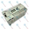
Operating as a standalone automation platform, the Omron C40P-CDR-A provides reliable control for legacy industrial processes. This block-style programmable logic controller integrates both discrete inputs and rugged relay outputs into a single, compact chassis. It is engineered with an internal universal AC power supply, making it highly adaptable for localized plant modifications, machinery retrofits, and reliable replacements in legacy control architectures.
Features
- Integrated layout containing 40 total discrete I/O channels in a single physical block.
- Robust electromechanical relay outputs capable of directly switching moderate inductive and resistive AC/DC loads.
- Built-in wide-range AC power supply module that operates directly on standard plant control voltages.
- Dedicated programming port designed for interface with legacy handheld consoles and peripheral software tools.
- Heavy-duty screw terminal strip allowing secure, direct physical wire connections.
Applications
- Legacy machinery retrofits and continuous manufacturing plant support operations.
- Small-scale material handling, packaging machinery, and dedicated conveyor systems.
- Basic municipal water treatment systems, pumping stations, and fan dampening controls.
Technical Specifications
| Parameter |
Value / Specification |
| Manufacturer |
Omron |
| Model Code |
C40P-CDR-A |
| Controller Series |
Sysmac C Series (C_P Class) |
| Total I/O Points |
40 Points |
| Input Configuration |
24 DC Inputs (24 VDC) |
| Output Configuration |
16 Relay Outputs (Electromechanical Contacts) |
| Input Power Supply |
100 to 240 VAC, 50/60 Hz |
| Mounting Configuration |
Direct Panel Mounting |
| Backup Memory Type |
RAM with Lithium Battery Backup / Optional ROM Option |
| Operating Temperature Range |
0 to 55 degC |
| Country of Origin |
Japan |
| Shipping Weight (Calculated) |
3.6 kg |
| Package Dimensions (Calculated) |
300 mm x 150 mm x 120 mm |
Connections and Interfaces
| Terminal Label |
Function / Assignment |
| L1, L2/N |
AC Input Power Terminals (100-240 VAC Line/Neutral) |
| LG / GR |
Line Ground and Frame Protective Earth Terminals |
| 00 to 11 (Ch 0) |
Discrete DC Inputs (Channels 0.00 to 0.11) |
| 00 to 11 (Ch 1) |
Discrete DC Inputs (Channels 1.00 to 1.11) |
| 00 to 07 (Ch 10) |
Discrete Relay Output Contacts (Channels 10.00 to 10.07) |
| 00 to 07 (Ch 11) |
Discrete Relay Output Contacts (Channels 11.00 to 11.07) |
Empirical Engineering Insights
Alternative Models & Compatibility
Direct code migration from this model to modern Sysmac CP1E or CP2E PLCs requires a complete ladder logic instruction translation. Key differences exist in the addressing mapping of data memory registers. Ensure that any replacement of legacy systems takes into physical consideration the differing footprint sizes and wiring layout orientations.
Application Pitfalls & Engineering Notes
The electromechanical relay contacts inside this module will degrade prematurely if used to drive highly inductive AC solenoid valves or contactor coils without external suppressors. Always wire a surge suppressor (RC snubber) across AC inductive loads, or a fast freewheeling diode across DC inductive loads to prevent contact welding and operational locking.
Commissioning & Wiring Tips
To maintain RAM program integrity during swap-outs, the internal backup lithium battery must only be replaced while the controller is powered ON. Alternatively, ensure the backup capacitor has been charged by keeping the power on for at least 15 minutes before executing a swift powered-down battery replacement within a 5-minute window.
Installation Guidelines
CRITICAL WARNING: Ensure all high-voltage AC input lines connected to L1 and L2/N terminals are fully isolated and locked out prior to handling terminations or removing the terminal block covers. Failure to de-energize the main panel feed may result in severe shock hazard and permanent electrical damage to the logic circuitry.
1
Mount the chassis onto a clean, flat metallic backplate inside an IP54-rated industrial control enclosure to preserve heat dissipation pathways.
2
Connect the 100-240 VAC supply power utilizing a minimum of 16 AWG insulated copper conductor to L1 and L2/N terminals, ensuring correct torque is applied.
3
Establish a low-impedance connection from the Line Ground terminal directly to the central chassis grounding busbar to mitigate external high-frequency electrical noise.
4
Verify that the total load draw of the combined outputs does not exceed the aggregate limit dictated by the internal terminal block common pins.