


Moving TwinCAT 3 Licenses with C9900-L100: Build and Device Checks
Before moving a TwinCAT 3 license with a Beckhoff C9900-L100, verify the TwinCAT build, XML device description, exact order code and cabinet limits.
Manufacturer: ABB
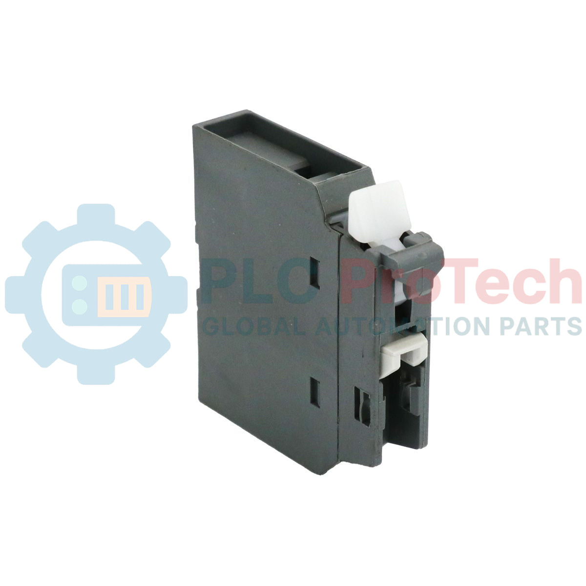
Product No.: 1SBN010110R1001 CA4-01
Country of origin:Sweden
Product Type: Auxiliary Contact Block
Barcode: 85371091
Payment: T/T, Western Union
Weight: 340g
Dimensions: 9.9 mm x 43 mm x 39.5 mm (W x H x D)
Shipping port: Xiamen
Warranty: 12 months
The ABB 1SBN010110R1001 is a front mounted auxiliary contact block designed for circuit signaling and control interface integration on AF block contactors and NF contactor relays. The CA4-01 features a 1-pole housing layout containing 1 N.C. instantaneous contact rated up to 690 V auxiliary circuit voltage. Fitted with screw terminals, it mounts directly to the front face of compatible AF(C)09(Z)(B)...96 contactors and NF(C)(Z)(B) contactor relays.
| Parameter | Details |
|---|---|
| Manufacturer | ABB |
| Product ID | 1SBN010110R1001 |
| Extended Product Type | CA4-01 |
| EAN | 3471523130029 |
| Number of Auxiliary Contacts NO | 0 |
| Number of Auxiliary Contacts NC | 1 |
| Number of Poles | 1P |
| Terminal Type | Screw Terminals |
| Rated Operational Voltage | Auxiliary Circuit 690 V |
| Rated Frequency (f) | Auxiliary Circuit 50 / 60 Hz |
| Conventional Free-air Thermal Current (Ith) | 16 A at Θ = 40 degC (acc. to IEC 60947-5-1) |
| Rated Operational Current AC-15 (Ie) | (24 / 127 V) 6 A, (220 / 240 V) 4 A, (400 / 440 V) 3 A, (500 V) 2 A, (690 V) 2 A |
| Rated Operational Current DC-13 (Ie) | (24 V) 6 A / 144 W, (48 V) 2.8 A / 134 W, (72 V) 1 A / 72 W, (110 V) 0.55 A / 60 W, (125 V) 0.55 A / 69 W, (220 V) 0.27 A / 60 W, (250 V) 0.27 A / 68 W, (400 V) 0.15 A / 60 W, (500 V) 0.13 A / 65 W, (600 V) 0.1 A / 60 W |
| Rated Short-time Withstand Current Low Voltage (Icw) | 140 A for 0.1 s, 100 A for 1 s |
| Rated Insulation Voltage (Ui) | 690 V (acc. to IEC 60947-5-1), 600 V (acc. to UL/CSA) |
| Rated Impulse Withstand Voltage (Uimp) | 6 kV |
| Maximum Electrical Switching Frequency | (AC-15) 1200 cycles per hour, (DC-13) 900 cycles per hour |
| Maximum Mechanical Switching Frequency | 3600 cycles per hour |
| Connecting Capacity Auxiliary Circuit | Flexible with Ferrule: 1/2x 0.75 ... 2.5 mm²; Flexible with Insulated Ferrule: 1x 0.75 ... 2.5 mm², 2x 0.75 ... 1.5 mm²; Rigid Solid: 1/2x 1 ... 2.5 mm²; Rigid Stranded: 1/2x 1 ... 2.5 mm² |
| Connecting Capacity Auxiliary Circuit UL/CSA | Rigid Solid: 1/2x 18-14 AWG; Rigid Stranded: 1/2x 18-14 AWG |
| Wire Stripping Length | Auxiliary Circuit 10 mm |
| Tightening Torque | Auxiliary Circuit 1.2 N·m (11 in·lb UL/CSA) |
| Degree of Protection | Auxiliary Terminals IP20 (acc. to IEC 60529, IEC 60947-1, EN 60529) |
| Product Net Width | 9.9 mm |
| Product Net Height | 43 mm |
| Product Net Depth / Length | 39.5 mm |
| Product Net Weight | 0.014 kg |
| Customs Tariff Number | 85389099 |
| Suitable For Models |
|---|
| AF09, AF09Z, AF12, AF12Z, AF16, AF16Z, AF26, AF26Z, AF30, AF30Z, AF38, AF38Z, AF40, AF52, AF65, AF80, AF96 |
| AFC09, AFC12, AFC16, AFC26, AFC30, AFC38, AFC40, AFC52, AFC65, AFC80, AFC96 |
| AF09B, AF09ZB, AF12B, AF12ZB, AF16B, AF16ZB, AF26B, AF26ZB, AF30B, AF30ZB, AF38B, AF38ZB, AF40B, AF52B, AF65B, AF80B, AF96B |
| NF22E, NFZ22E, NF31E, NFZ31E, NF40E, NFZ40E |
| NFC22E, NFC31E, NFC40E, NFZB22E, NFB22E, NFZB31E, NFB31E, NFZB40E, NFB40E |


Global Express Shipping
Returns & Warranty




Global Express Shipping
Returns & Warranty
Orders are processed and delivered Monday-Friday (excluding public holidays).
For full eligibility, restocking fees, and international return details, please view our official Refund & Return Policy .
| Color pattern |
Greyish White
|
| Country of origin |
Sweden
|

Before moving a TwinCAT 3 license with a Beckhoff C9900-L100, verify the TwinCAT build, XML device description, exact order code and cabinet limits.

A field checklist for replacing a Beckhoff EL4032, covering the ±10 V load, terminal map, power contacts, EtherCAT state, and watchdog behavior.

Before replacing a Yokogawa AAI835, verify the 4-in/4-out channel map, power-loss loop behavior, barrier type, output load, cable, and redundancy.

ABB PM891K01 article 3BSE053241R1 is the non-redundant AC 800M processor kit. Use this field checklist before replacement.

Replacement checks for ABB TP853 3BSE018126R1: identify the installed CI853, CI855, CI857, or CI861 interface, record wiring, and verify communication after installation.

Engineering checks for the Allen-Bradley 5069-L330ERMS2: controller capacity, separate RTB kits, local I/O limits, network-node limits, and motion-axis count.