


1756-OF4 Output Wrong? Check Mode, RTB, and Scaling First
A field-first diagnostic sequence for 1756-OF4 analog output problems: channel mode, removable terminal block, scaling, and controlled electrical checks.
Manufacturer: ABB
Product No.: INTKM01
Country of origin:India
Product Type: Time Keeper Master Module
Barcode: 8538908180
Payment: T/T, Western Union
Weight: 500g
Dimensions: 358.14 mm x 271.78 mm (H x W)
Shipping port: Xiamen
Warranty: 12 months
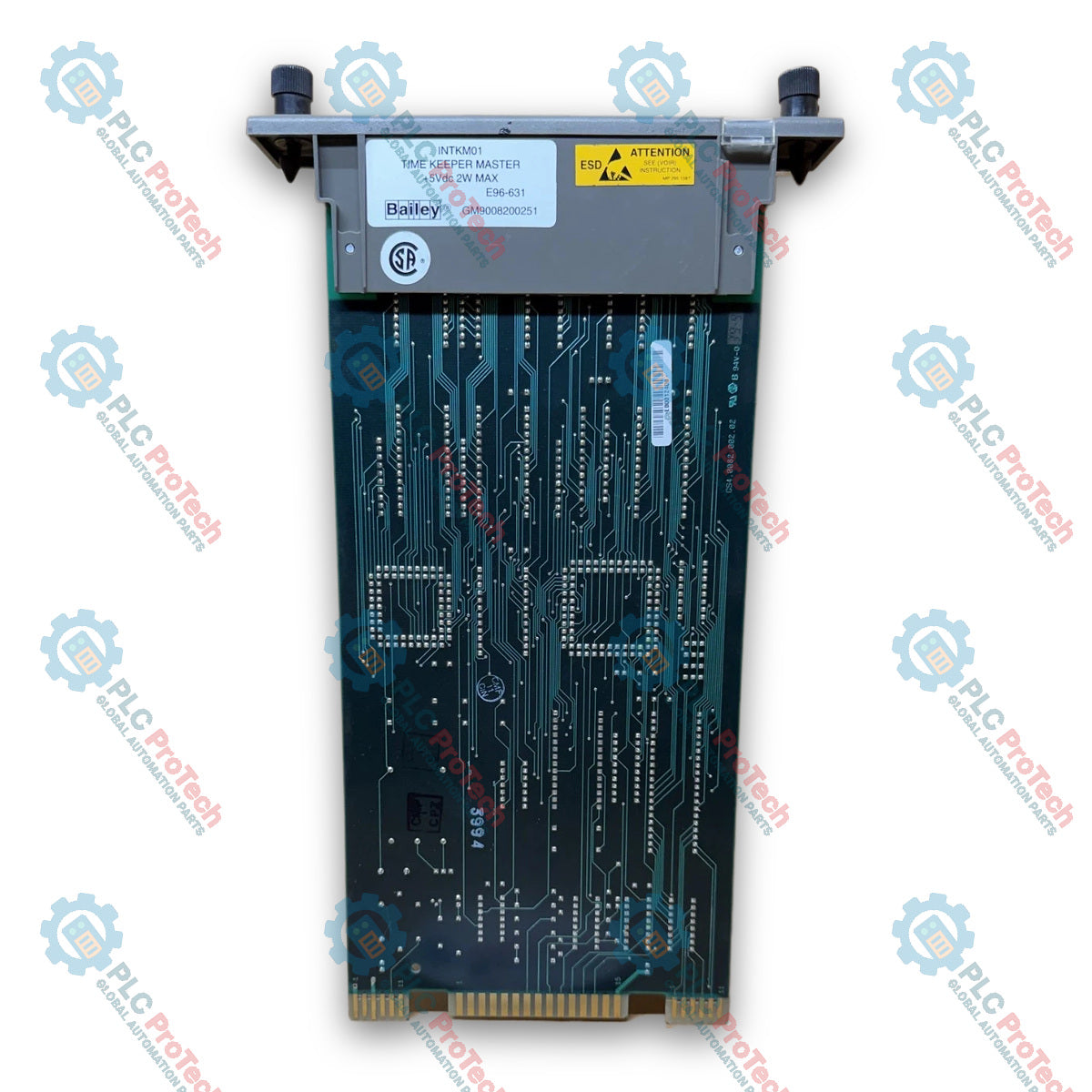
The ABB Bailey INTKM01 is an INFI 90 Time Keeper Master Module designed for time synchronization in Sequence of Events systems.
The module provides the master timing reference for the SOE architecture. It distributes synchronized timing information to connected time-keeper modules and exchanges absolute time data through the I/O Expander Bus.
The INTKM01 uses three card-edge connectors identified as P1, P2, and P3. P1 provides module power and receives the power-fail interrupt. P2 connects the module to the I/O Expander Bus. P3 handles time synchronization signals and receives IRIG-B timing information from the NTST01 termination unit.
The photographed module is marked INTKM01 TIME KEEPER MASTER, +5Vdc 2W MAX, E96-631, and GM9008200251.
The INTKM01 uses three card-edge connectors:
| Connector | Function |
|---|---|
| P1 | Module power and power-fail interrupt |
| P2 | I/O Expander Bus |
| P3 | Time synchronization and IRIG-B interface |
| Pin | Function |
|---|---|
| 1 | +5 VDC |
| 2 | +5 VDC |
| 3 | NC |
| 4 | NC |
| 5 | GND (5 VDC) |
| 6 | GND (5 VDC) |
| 7 | NC |
| 8 | NC |
| 9 | PFI |
| 10 | NC |
| 11 | NC |
| 12 | NC |
PFI is the power-fail interrupt signal received from the power supply unit.
| Pin | Function |
|---|---|
| 1 | Data bit 1 |
| 2 | Data bit 0 |
| 3 | Data bit 3 |
| 4 | Data bit 2 |
| 5 | Data bit 5 |
| 6 | Data bit 4 |
| 7 | Data bit 7 |
| 8 | Data bit 6 |
| 9 | Bus clock |
| 10 | Sync |
| 11 | NC |
| 12 | NC |
P2 provides the module interface to the INFI 90 I/O Expander Bus for data transfer and synchronization.
| Pin | Function |
|---|---|
| 1 | NC |
| 2 | NC |
| 3 | NC |
| 4 | NC |
| 5 | NC |
| 6 | NC |
| 7 | IRIG B+ |
| 8 | Reserved |
| 9 | Reserved |
| 10 | Rx presence NTST01+ |
| 11 | Reserved |
| 12 | Tx sync time information+ |
| 13 | Reserved |
| 14 | NC |
| 15 | GND |
| A | NC |
| B | NC |
| C | NC |
| D | NC |
| E | NC |
| F | NC |
| H | IRIG B- |
| J | Reserved |
| K | Reserved |
| L | Rx presence NTST01- |
| M | Reserved |
| N | Tx sync time information- |
| P | Reserved |
| R | NC |
| S | NC |
| Signal | Function |
|---|---|
| IRIG B+ / IRIG B- | Differential IRIG-B time reference input |
| Rx presence NTST01+ / - | Detects the NTST01 timing receiver interface |
| Tx sync time information+ / - | Differential synchronized time output |
| PFI | Power-fail interrupt |
| Bus Clock | I/O Expander Bus clock |
| Sync | I/O Expander Bus synchronization |
INFI 90 Time Keeper Master Module
Master time synchronization for Sequence of Events systems
IRIG-B external time reference capability
Internal clock synchronization and correction
Time-sync distribution to IMSET01 modules
Communication through NTST01 termination hardware
Absolute time interface to the INSEM01 Sequence of Events Master
RS-485 time synchronization output
Internal timing operation when the external receiver is unavailable
Two-color module status indication
Diagnostic operating mode
Exact hardware marking INTKM01
Nameplate power marking +5Vdc, 2 W maximum
INFI 90 Sequence of Events systems
Distributed event time synchronization
Plant event chronology
SOE timestamp coordination
Master clock distribution
Legacy Bailey control-system maintenance
Replacement of installed INTKM01 Time Keeper Master modules
| Parameter | Specification |
|---|---|
| Manufacturer | ABB Bailey |
| Exact Model | INTKM01 |
| Product Type | Time Keeper Master Module |
| System Family | INFI 90 |
| Primary Function | Sequence of Events time synchronization |
| Associated SOE Master | INSEM01 |
| Associated Time Keeper Module | IMSET01 |
| Associated Termination Unit | NTST01 |
| Nameplate Identification | INTKM01 TIME KEEPER MASTER |
| Additional Nameplate Marking | E96-631 |
| Hardware / Unit Marking | GM9008200251 |
| Parameter | Specification |
|---|---|
| Nameplate Supply | +5 VDC |
| Nameplate Power | 2 W maximum |
| Parameter | Specification |
|---|---|
| External Time Input | IRIG-B |
| IRIG-B Format | DC level shift |
| IRIG-B Interface | Through NTST01 |
| Time-Sync Output | RS-485 |
| Time-Sync Data Rate | 62.6 kbaud |
| Synchronization Resolution | +/-10 microseconds |
| Absolute Time Resolution to INSEM01 | +/-1 ms |
| Internal Oscillator Frequency | 10 MHz |
| Oscillator Stability | +/-1 ppm |
| Oscillator Aging | 1 ppm/year |
| Parameter | Specification |
|---|---|
| Processor | DSP 2101 |
| CPU Architecture | 16-bit |
| CPU Frequency | 10 MHz |
| Instruction Cycle | 100 ns |
| Timer | 16-bit interval timer with prescaler |
| Serial Port | 1 bidirectional synchronous serial port |
| Boot EPROM | 64 kbyte |
| RAM | 16 kword |
| FIFO | 512 byte |
| Program Memory RAM | 1 kword |
| Data Memory RAM | 512 word |
| Interface | Function |
|---|---|
| IRIG-B | Receives external reference time through NTST01 |
| Time-Sync Link | Distributes synchronized time to IMSET01 modules |
| I/O Expander Bus | Transfers absolute time to INSEM01 |
| RS-485 | Time synchronization link to downstream SOE modules |
| NTST01 | Termination and timing signal interface |
The INTKM01 receives time information from the NTST01 through the IRIG-B interface.
When a valid external time receiver is present, the module periodically adjusts its internal clock against that reference.
The module provides absolute time to the INSEM01 through the I/O expander bus. It also distributes synchronized timing to IMSET01 modules through the time-sync link.
If the external receiver is lost, the INTKM01 continues generating time using its internal quartz timing reference.


Global Express Shipping
Returns & Warranty


Global Express Shipping
Returns & Warranty
Orders are processed and delivered Monday-Friday (excluding public holidays).
For full eligibility, restocking fees, and international return details, please view our official Refund & Return Policy .
| Country of origin |
India
|

A field-first diagnostic sequence for 1756-OF4 analog output problems: channel mode, removable terminal block, scaling, and controlled electrical checks.

A direct comparison of 1746-OA8 and 1746-OA16 output count, common grouping, backplane current and temperature-derated load limits.

A field checklist for recording the 1761-NET-DNI hardware series, firmware, EDS file, DF1 settings, DeviceNet address and messaging configuration before replacement.

The EL3062 is a 0–10 V EtherCAT terminal. The EL3062-0030 is a 0–30 V variant. This checklist covers identification, scaling and commissioning.

A field checklist for replacing Allen-Bradley 1769-OW8 relay output modules without losing load-group, wiring, and commissioning details.

A field checklist for matching PLC digital and analog I/O to sensors, loads, commons, isolation groups, filters, and replacement settings.