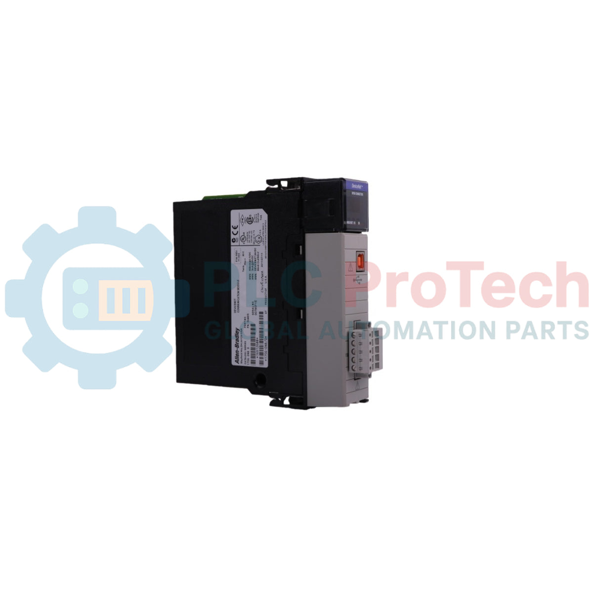
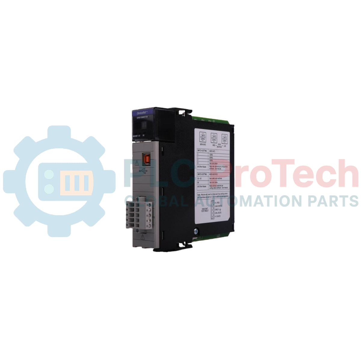
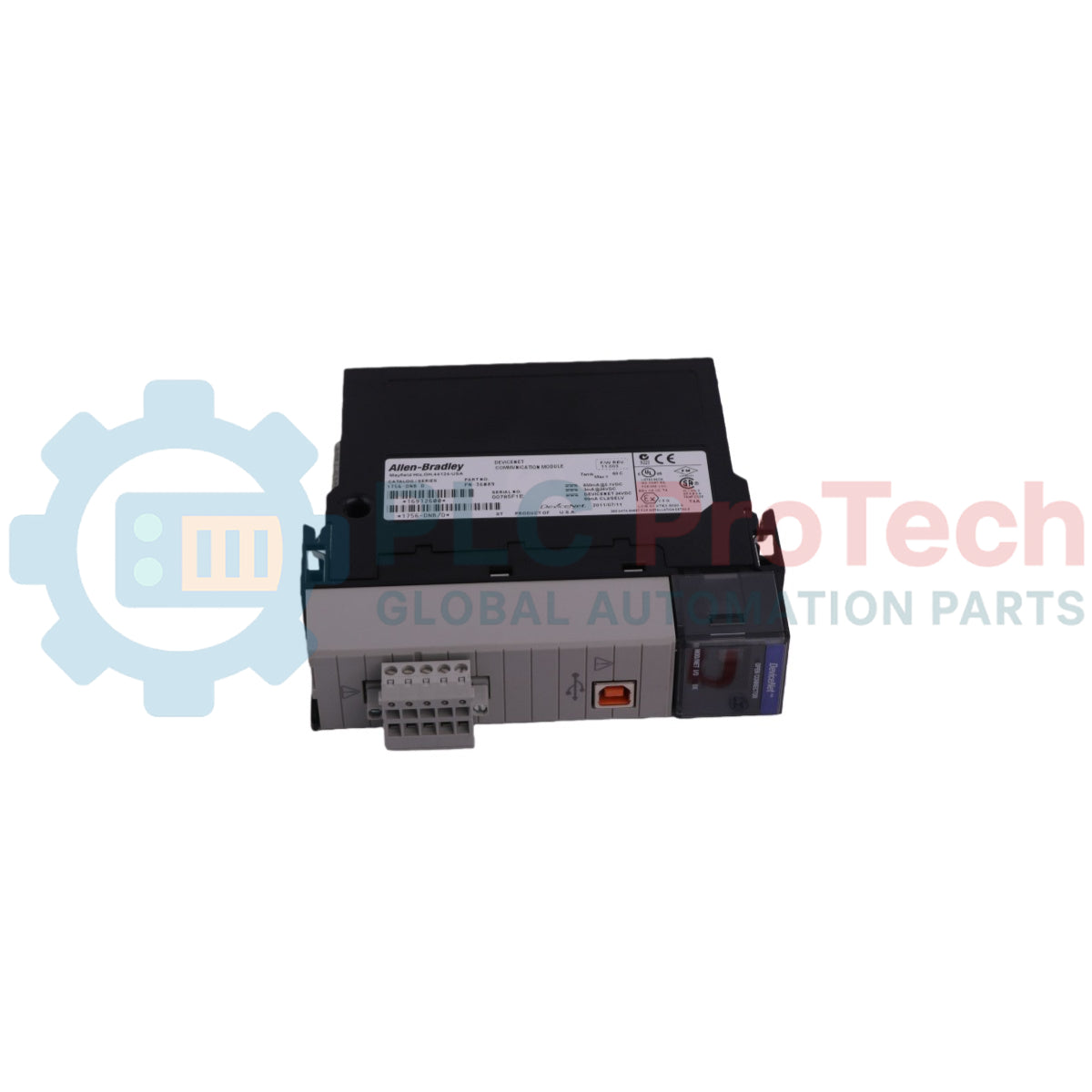
The 1756-DNB is a ControlLogix DeviceNet scanner module that acts as an interface between the ControlLogix system backplane and devices on a DeviceNet network. The 1756-DNB communicates with DeviceNet devices to read input data, write output data, and manage configuration parameters via predefined ControlLogix controller I/O and status structures. It features a front-panel 4-character alphanumeric display and status indicators for system diagnostics, rotary switches for data rate and node address settings, a USB 1.1 device port for programming and configuration, and an open-style DeviceNet interface connector.
Features
Fits into any slot of a ControlLogix chassis with support for multiple scanner modules in the same chassis.
Features an onboard 4-character alphanumeric display for diagnostics, error code reporting, and node monitoring.
Equipped with front/top-accessible rotary switches to set network communication rate and DeviceNet node address.
Integrated USB 1.1 Series B device port for direct PC programming, configuration, and firmware updates.
Supports up to 123 words of output data, 124 words of input data, and status data registers across the backplane.
Includes MOD/NET, I/O, and OK bi-color status indicators for network, I/O scanning, and module status.
Applications
DeviceNet network control and monitoring in ControlLogix PLC systems.
Interfacing field sensors, actuators, motor starters, and drives to ControlLogix controllers.
Industrial automation networks requiring distributed device data acquisition and control.
Technical Specifications
Parameter
Value
Manufacturer
Allen-Bradley / Rockwell Automation
Catalog Number
1756-DNB
Module Location
Any slot in the ControlLogix chassis
DeviceNet Communication Rate
125 Kbps (500 m max), 250 Kbps (250 m max), 500 Kbps (100 m max)
Backplane Current (5.1V DC)
850 mA
Backplane Current (24V DC)
3 mA
DeviceNet Current (Max)
11...25V DC (60 mA max)
Power Dissipation (Max)
5.8 W
Thermal Dissipation (Max)
19.8 BTU/hr
Isolation Voltage
30V continuous (Basic Insulation Type), tested at 500V AC for 60 s (DeviceNet to system)
Enclosure Type Rating
None (open-style)
Operating Temperature
0...60 degC (32...140 degF)
Storage Temperature
-40...85 degC (-40...185 degF)
Relative Humidity
5...95% noncondensing
Operating Vibration
2 g @ 10...500 Hz
Operating Shock
30 g
Nonoperating Shock
50 g
USB Port
USB 1.1 Device, USB Series B Receptacle
Recommended USB Cable
Samtec cable, PN RSP-119350
DeviceNet Connector Torque
0.56...0.79 Nm (5...7 in-lb)
North American Temp Code
T4A
IEC Temp Code
T4
Connections/Interfaces
Connector Pin
Function
V- (Black)
DeviceNet Power Return / Black Wire
CAN_L (Blue)
DeviceNet CAN Low Signal / Blue Wire
SHIELD (Bare)
DeviceNet Cable Shield / Bare Wire
CAN_H (White)
DeviceNet CAN High Signal / White Wire
V+ (Red)
DeviceNet 24V DC Power / Red Wire
Installation Guidelines
Align the circuit board with the top and bottom guides in the ControlLogix chassis and slide the module into the slot until it is flush with other modules.
Mount inside an enclosure that provides appropriate environmental protection and requires a tool for interior access.
Wire the DeviceNet open-style linear plug matching the color-coded terminals (Red: V+, White: CAN_H, Bare: Shield, Blue: CAN_L, Black: V-).
Ensure proper DeviceNet network power supply compliance (SELV/PELV for CE LVD; Class 2 or Limited Voltage/Current for UL).
Avoid setting or changing the rotary switch communication rate while connected to an active network.
Use a maximum 3.0 m USB cable without hubs for temporary programming or configuration connections.
Compliance and Certifications
UL Listed Industrial Control Equipment (UL File E65584)
UL Listed for Class I, Division 2 Group A, B, C, D Hazardous Locations (UL File E194810)
CSA Certified Process Control Equipment (CSA File LR54689C)
CSA Certified Process Control Equipment for Class I, Division 2 Group A, B, C, D Hazardous Locations (CSA File LR69960C)
FM Approved Equipment for Class I, Division 2 Group A, B, C, D Hazardous Locations
European Union ATEX Directive 94/9/EC compliant (EN 60079-15, Zone 2 Protection "n")
European Union EMC Directive 2004/108/EC compliant (EN 61326-1, EN 61000-6-2, EN 61000-6-4, EN 61131-2)
Australian Radiocommunications Act compliant (AS/NZS CISPR 11)
ODVA conformance tested to DeviceNet specifications
FAQ
What communication rates are supported by the module?
The module supports DeviceNet network communication rates of 125 Kbps, 250 Kbps, and 500 Kbps.
How can the node address and data rate be set on the device?
The node address and data rate can be configured using the physical rotary switches on the device or electronically via RSNetWorx for DeviceNet software.
What is the recommended storage temperature for the communication module?
The nonoperating storage temperature range for the communication module is from -40 degC to +85 degC.
What function does the USB port on the front panel serve?
The USB 1.1 device port provides a temporary connection for downloading programs to controllers, configuring modules, and updating firmware via RSLinx software.
A practical replacement guide for the GE Fanuc IC693CPU313, covering its embedded five-slot architecture, memory backup, firmware-dependent capacity and why it cannot use Series 90-30 expansion racks.
A field-focused comparison of Bently Nevada 3500/40M and 3500/42M monitor inputs, channel-pair configuration, rear I/O options, external termination hardware and firmware checks before replacement.
A field checklist for diagnosing Allen-Bradley 1746-NR4 RTD and resistance inputs, including sensor curves, lead compensation, excitation current, filter timing and channel diagnostics.
A field-focused checklist for replacing an Allen-Bradley 1785-L40B or planning a PLC-5/40 migration, covering backups, 1771 I/O mapping, DH+/RIO channels, revision risks and commissioning.
Replacing an Allen-Bradley 1747-SN scanner? Check SLC 500 logical rack and G-file mapping, link speed, cable termination, COMM/FAULT LEDs and hardware series before blaming the module or changing the...