


ABB PM891K01 Replacement: Check Redundancy Before Ordering
ABB PM891K01 article 3BSE053241R1 is the non-redundant AC 800M processor kit. Use this field checklist before replacement.
Manufacturer: Allen-Bradley
Product No.: 1761-L32AWA
Country of origin:United States
Product Type: MicroLogix 1000 Controller Unit
Barcode: 8537101190
Payment: T/T, Western Union
Weight: 900g
Dimensions: 200 x 80 x 73 mm (W x H x D)
Shipping port: Xiamen
Warranty: 12 months
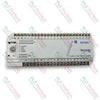
The 1761-L32AWA is a fixed-I/O MicroLogix 1000 programmable controller for standalone machine and process control. It integrates an AC power supply, processor, memory, discrete I/O, and serial communication functions.
The controller provides 20 digital inputs for 120V AC field signals and 12 relay outputs. The relay contacts can switch supported AC or DC loads used by contactors, motor starters, solenoids, indicators, and other control devices.
A built-in RS-232 interface supports DF1 communication for programming, monitoring, and controller communication. The control program is retained in nonvolatile EEPROM memory.
The compact controller supports DIN rail or screw mounting inside an industrial enclosure. Horizontal mounting provides the full specified operating temperature range.
| Parameter | Information |
|---|---|
| Catalog Number | 1761-L32AWA |
| Unique Product Identifier | 1761-L32AWA |
| UPC | 662468368704 |
| Product Description | MicroLogix 1000, 120/240V AC power, 20 120V AC digital inputs, and 12 relay outputs |
| Product Class | Controller |
| Parameter | Specification |
|---|---|
| Brand | Allen-Bradley |
| Catalog Number | 1761-L32AWA |
| Product Family | MicroLogix 1000 |
| Product Type | Fixed-I/O Programmable Controller |
| Total Digital I/O | 32 points |
| Digital Inputs | 20 |
| Input Type | 120V AC |
| Digital Outputs | 12 |
| Output Type | Relay |
| Communication | DF1 |
| Communication Interface | RS-232 |
| Memory | 1K EEPROM |
| Program and Data Capacity | Approximately 737 instruction words and 437 data words |
| Parameter | Specification |
|---|---|
| Nominal Power Supply | 120/240V AC |
| Power Supply Voltage Range | 85...264V AC |
| Input Frequency | 47...63 Hz |
| Power Usage at 120V AC | 19 VA |
| Power Usage at 240V AC | 25 VA |
| Maximum Inrush Current | 30 A for 8 ms |
| Minimum Power Cycles | 50,000 |
| Parameter | Specification |
|---|---|
| Input Controller Class | 100...120V AC |
| Input Voltage Range | 79...132V AC |
| Input Frequency Range | 47...63 Hz |
| Minimum On-State Voltage | 79V AC |
| Maximum On-State Voltage | 132V AC |
| Off-State Voltage | 20V AC |
| Minimum On-State Current | 5.0 mA at 79V AC, 47 Hz |
| Nominal On-State Current | 12.0 mA at 120V AC, 60 Hz |
| Maximum On-State Current | 16.0 mA at 132V AC, 63 Hz |
| Maximum Off-State Current | 2.5 mA |
| Nominal Input Impedance at 50 Hz | 12K ohm |
| Nominal Input Impedance at 60 Hz | 10K ohm |
| Maximum Input Inrush | 250 mA |
| Parameter | Specification |
|---|---|
| Output Type | Relay |
| Minimum Load Current | 10.0 mA |
| Maximum Load per Controller | 1440 VA |
| Maximum Current per Common | 8.0 A |
| Maximum Off-State Leakage Current | 0 mA |
| Off-to-On Response | 10 ms maximum |
| On-to-Off Response | 10 ms maximum |
| Mechanical Relay Life | 20,000,000 cycles |
| Maximum Voltage | Make Current | Break Current | Continuous Current | Make Rating | Break Rating |
|---|---|---|---|---|---|
| 240V AC | 7.5 A | 0.75 A | 2.5 A | 1800 VA | 180 VA |
| 120V AC | 15 A | 1.5 A | 2.5 A | 1800 VA | 180 VA |
| 125V DC | 0.22 A | 0.22 A | 1.0 A | 28 VA | 28 VA |
| 24V DC | 1.2 A | 1.2 A | 2.0 A | 28 VA | 28 VA |
Do not exceed the specified current per common. For DC applications, relay make and break ratings depend on the applied voltage.
| Parameter | Specification |
|---|---|
| Width | 200 mm (7.87 in.) |
| Height | 80 mm (3.15 in.) |
| Depth | 73 mm (2.87 in.) |
| Mounting Methods | DIN rail or mounting screws |
| Recommended Minimum Clearance | 50.8 mm (2 in.) at the top, bottom, and sides |
| Maximum Terminal Screw Torque | 0.9 N.m (8.0 in.lb) |
| Parameter | Specification |
|---|---|
| Solid Wire Size | 14...22 AWG |
| Stranded Wire Size | 16...22 AWG |
| Maximum Conductors per Terminal Screw | 2 |
| Recommended Spade Lug for 22...16 AWG | AMP 53120-1 or equivalent |
| Recommended Spade Lug for 16...14 AWG | AMP 53123-1 or equivalent |
| Terminal Screw Head Diameter | 5.5 mm (0.220 in.) |
| Parameter | Specification |
|---|---|
| Operating Temperature, Horizontal Mounting | 0...55 degC |
| Operating Temperature, Vertical Mounting | 0...40 degC |
| Storage Temperature | -40...85 degC |
| Operating Humidity | 5...95%, noncondensing |
| Operating Vibration, Panel Mounted | 5 Hz...2 kHz, 0.381 mm peak-to-peak, 2.5g, 1 hour per axis |
| Nonoperating Vibration | 5 Hz...2 kHz, 0.762 mm peak-to-peak, 5g, 1 hour per axis |
| Operating Shock | 10g peak acceleration |
| Operating Shock, DIN Rail Mounted | 7.5g peak acceleration |
| Nonoperating Shock | 20g peak acceleration |
| Isolation | 1500V AC |
| Electrostatic Discharge | EN 61000-2 at 8 kV |
| Fast Transient | EN 61000-4 at 2 kV on power supply and I/O; 1 kV on communication circuits |
Relay-equipped 32-point controllers require an additional 2.5g derating for the specified shock rating.
| Interface | Function |
|---|---|
| AC Power Input | Supplies operating power from a 120/240V AC source |
| Digital Inputs I/0...I/19 | Accept 20 discrete 120V AC input signals |
| Relay Outputs O/0...O/11 | Switch 12 supported AC or DC output loads |
| Output Common Terminals | Provide common connections for relay output groups |
| RS-232 Port | Supports DF1 programming and controller communication |
| Functional Earth Terminal | Provides a low-impedance earth path for noise immunity |
| Certification | Specification |
|---|---|
| C-UL | Class I, Division 2, Groups A, B, C, and D, when marked |
| UL | UL Listed for Class I, Division 2, Groups A, B, C, and D, when marked |
| CE | Compliant with applicable directives |
| RCM | Compliant with applicable directives |
| EAC | Compliant with applicable directives |
| Hazardous Location Suitability | Class I, Division 2, Groups A, B, C, and D, or nonhazardous locations when marked |


Global Express Shipping
Returns & Warranty


| Product Image | Model Number / Title | Condition | Availability | Action |
|---|---|---|---|---|
|
Allen-Bradley 1761-L32BWB MicroLogix 1000 Controller Processor | Original New | In Stock | View Details |
Global Express Shipping
Returns & Warranty
Orders are processed and delivered Monday-Friday (excluding public holidays).
For full eligibility, restocking fees, and international return details, please view our official Refund & Return Policy .
| Color pattern |
Greyish White
|
| Country of origin |
United States
|
| Power source |
AC-powered
|

ABB PM891K01 article 3BSE053241R1 is the non-redundant AC 800M processor kit. Use this field checklist before replacement.

Replacement checks for ABB TP853 3BSE018126R1: identify the installed CI853, CI855, CI857, or CI861 interface, record wiring, and verify communication after installation.

Engineering checks for the Allen-Bradley 5069-L330ERMS2: controller capacity, separate RTB kits, local I/O limits, network-node limits, and motion-axis count.

Checks to record before replacing ABB 3HNE 00006-1 DSQC 351: controller generation, X3/X5/X20/X21 wiring, DeviceNet settings, INTERBUS mapping, and LED states.

Compare the IC693CPU360 and IC693CPU364 by Ethernet interface, +5 VDC load, memory, rack limits, and replacement checks.

A field-first diagnostic sequence for 1756-OF4 analog output problems: channel mode, removable terminal block, scaling, and controlled electrical checks.