


Implementing 3-Switch XOR Ladder Logic with Internal Bit
Implement a 3-SPST switch XOR light circuit in LogixPro or RSLogix 500 using an internal relay bit. Includes truth tables, boolean equations, and verified.

Designed to expand the manual control capabilities of CP6x13-00xx and CP7x13-00xx control panels, the Beckhoff C9900-E731 is a physical push-button extension designed for right-side installation. It integrates directly with 15-inch touch screen systems that do not feature built-in hardware keyboards. This module bridges physical tactile control and digital systems, offering independent physical contact routing for critical operator commands.
| Specification Parameter | Value / Rating |
|---|---|
| Manufacturer | Beckhoff Automation GmbH & Co. KG |
| Model Number | C9900-E731 |
| Compatible Panels | CP6x13-00xx and CP7x13-00xx (15-inch displays without keyboard) |
| Mounting Location | Right side of host Control Panel / Panel PC |
| Push-Button Type | 20 x Siemens Signum square keys (30 x 30 mm) |
| Indicator Lamps | Integrated within the 20 push-buttons (USB controlled) |
| Emergency Stop Key | 1 x Siemens Signum Emergency Stop (Direct wireable) |
| Contact Configurations | 1st NO contact via USB; 2nd NO contact via hardwired terminal row |
| Lifecycle Status | Service Phase (Legacy support) |
| Shipping Weight (Calculated) | 5.0 kg |
| Connector / Interface | Function / Circuit Assignment |
|---|---|
| USB Connection | Transmits 1st NO contact signals and receives control inputs for all indicator lamps. |
| Internal Terminal Row | Direct access point for wiring the independent 2nd NO contacts of the 20 push-buttons. |
| E-Stop Terminals | Direct-wire interface for dual-channel emergency stop integration to external safety relays. |
The C9900-E731 is currently in its service phase. When retrofitting or replacing this unit, confirm that your existing host control panel features a 15-inch display without a physical keyboard (specifically models CP6x13 or CP7x13). This extension is mechanically tailored for right-side mounting only; left-side mount options require different model designations due to enclosure profile alignments.
Safety Integration Notice: Under no circumstances should the USB communication interface be used to process safety-critical controls. The first contact (USB) is for visualization or standard control routines. High-safety functions—such as the integrated Emergency Stop and the secondary physical NO contacts—must be wired directly through the terminal row to an approved, dual-channel safety relay or a functional TwinSAFE terminal (e.g., Beckhoff EL1904).
When routing the direct wiring lines from the terminal row alongside the USB communication cable, utilize shielded cabling for the digital signals. High-frequency electromagnetic interference from nearby variable frequency drives (VFDs) can induce electrical noise on unshielded lines, resulting in false state transitions within the controller's input registers.
CRITICAL WARNING:
Before starting any installation or maintenance, verify that all power to the Panel PC and control circuits is disconnected. Lock out and tag out all auxiliary power lines routed to the internal terminal row to prevent electric shock and unintended system startup.
Position the C9900-E731 extension against the right edge of the CP6x13 or CP7x13 panel. Verify that the sealing gasket is correctly seated around the mating lip to maintain IP65 integrity.
Secure the mechanical connection screws sequentially to ensure uniform compression of the structural sealing profile.
Connect the internal USB interface cable directly to a designated USB host port on the rear processing unit of the control panel.
Route physical safety conductors from the Emergency Stop switch and secondary NO contacts to the system terminal strip, using separate cable glands to keep safety lines clean of high-power cables.
Global Express Shipping
Returns & Warranty

Manufacturer: BECKHOFF
Product No.: C9900-E731
Country of origin:Germany
Product Type: Industrial HMI Accessories
Payment: T/T, Western Union
Weight: 500g
Dimensions: drawings with dimensions of the push-button e x tensions as AutoCAD DXF file
Shipping port: Xiamen
Warranty: 12 months
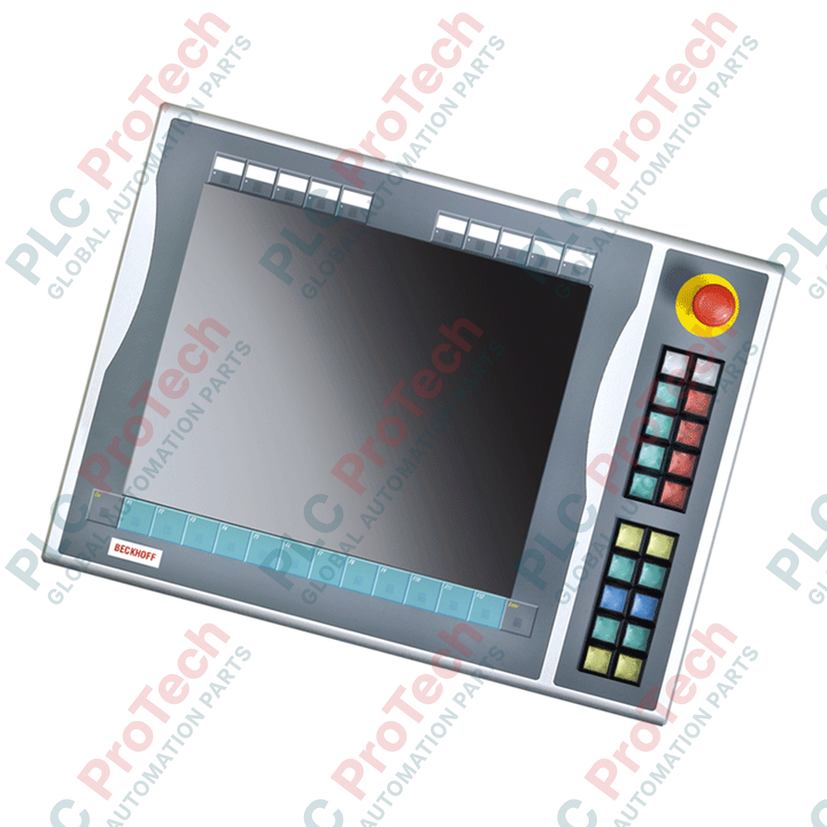
Designed to expand the manual control capabilities of CP6x13-00xx and CP7x13-00xx control panels, the Beckhoff C9900-E731 is a physical push-button extension designed for right-side installation. It integrates directly with 15-inch touch screen systems that do not feature built-in hardware keyboards. This module bridges physical tactile control and digital systems, offering independent physical contact routing for critical operator commands.
| Specification Parameter | Value / Rating |
|---|---|
| Manufacturer | Beckhoff Automation GmbH & Co. KG |
| Model Number | C9900-E731 |
| Compatible Panels | CP6x13-00xx and CP7x13-00xx (15-inch displays without keyboard) |
| Mounting Location | Right side of host Control Panel / Panel PC |
| Push-Button Type | 20 x Siemens Signum square keys (30 x 30 mm) |
| Indicator Lamps | Integrated within the 20 push-buttons (USB controlled) |
| Emergency Stop Key | 1 x Siemens Signum Emergency Stop (Direct wireable) |
| Contact Configurations | 1st NO contact via USB; 2nd NO contact via hardwired terminal row |
| Lifecycle Status | Service Phase (Legacy support) |
| Shipping Weight (Calculated) | 5.0 kg |
| Connector / Interface | Function / Circuit Assignment |
|---|---|
| USB Connection | Transmits 1st NO contact signals and receives control inputs for all indicator lamps. |
| Internal Terminal Row | Direct access point for wiring the independent 2nd NO contacts of the 20 push-buttons. |
| E-Stop Terminals | Direct-wire interface for dual-channel emergency stop integration to external safety relays. |
The C9900-E731 is currently in its service phase. When retrofitting or replacing this unit, confirm that your existing host control panel features a 15-inch display without a physical keyboard (specifically models CP6x13 or CP7x13). This extension is mechanically tailored for right-side mounting only; left-side mount options require different model designations due to enclosure profile alignments.
Safety Integration Notice: Under no circumstances should the USB communication interface be used to process safety-critical controls. The first contact (USB) is for visualization or standard control routines. High-safety functions—such as the integrated Emergency Stop and the secondary physical NO contacts—must be wired directly through the terminal row to an approved, dual-channel safety relay or a functional TwinSAFE terminal (e.g., Beckhoff EL1904).
When routing the direct wiring lines from the terminal row alongside the USB communication cable, utilize shielded cabling for the digital signals. High-frequency electromagnetic interference from nearby variable frequency drives (VFDs) can induce electrical noise on unshielded lines, resulting in false state transitions within the controller's input registers.
CRITICAL WARNING:
Before starting any installation or maintenance, verify that all power to the Panel PC and control circuits is disconnected. Lock out and tag out all auxiliary power lines routed to the internal terminal row to prevent electric shock and unintended system startup.
Position the C9900-E731 extension against the right edge of the CP6x13 or CP7x13 panel. Verify that the sealing gasket is correctly seated around the mating lip to maintain IP65 integrity.
Secure the mechanical connection screws sequentially to ensure uniform compression of the structural sealing profile.
Connect the internal USB interface cable directly to a designated USB host port on the rear processing unit of the control panel.
Route physical safety conductors from the Emergency Stop switch and secondary NO contacts to the system terminal strip, using separate cable glands to keep safety lines clean of high-power cables.
| Product Image | Model Number / Title | Condition | Availability | Action |
|---|---|---|---|---|

|
Allen-Bradley 2711P-T15C4D9 PanelView Plus 6 Terminal | Original New | In Stock | View Details |
Global Express Shipping
Returns & Warranty
Orders are processed and delivered Monday-Friday (excluding public holidays).
For full eligibility, restocking fees, and international return details, please view our official Refund & Return Policy .
| Country of origin |
Germany
|

Implement a 3-SPST switch XOR light circuit in LogixPro or RSLogix 500 using an internal relay bit. Includes truth tables, boolean equations, and verified.

Integrate Allen-Bradley CompactLogix, Caterpillar ATS, and generators into DeltaV DCS over Modbus RTU. Covers ProSoft MVI69-MCM, Miille DIN266 gateways.

ONS instruction fires but the OTE coil never latches in Studio 5000 because the one-shot is only true for one scan. Use OTL/OTU or seal-in logic instead.

Configure Allen-Bradley Kinetix 5500 servo drives on EtherNet/IP. Covers CIP Sync, IEEE 1588 V2 timing, Stratix selection, DLR topology, and HMI.

A moving-average filter is the sliding-window smoother most instrument engineers drop into DCS and PLC analog paths. Here is how the window works, how N and sample time set lag, and when a...

On Frame 5–9 gas turbines, GE Mark VI and Mark VIe run control as function-block application software. This article maps process, protection, and sequencing functions—and what Toolbox ST access...