BECKHOFF

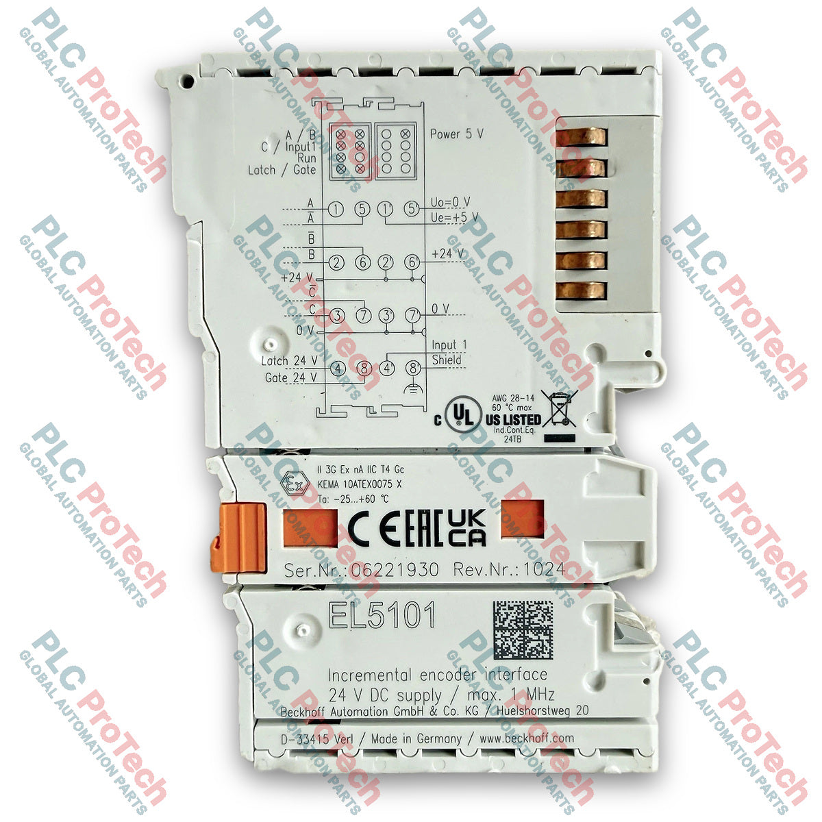
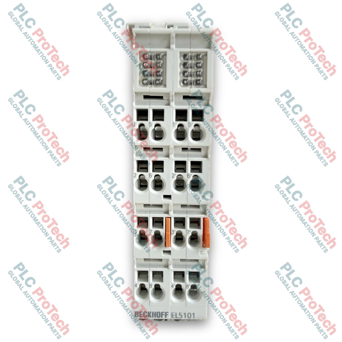
Beckhoff EL5101 EtherCAT Terminal Incremental Encoder Interface

SKU EL5101

In stock
  • 12-month warranty
  • Free returns within 30 days
  • Manufacturer: BECKHOFF
  • Product No.: EL5101
  • Origin Germany
  • Product Type: EtherCAT Terminal
  • Payment: T/T, Western Union
  • Weight: 2.0 kg
  • Dimensions: 120 mm x 80 mm x 35 mm
  • Shipping port: Xiamen
  • Warranty: 12 months

Tags

Product Documentation

Technical Datasheet (PDF) Complete specifications and technical drawings.

Technical Datasheet

Beckhoff EL5101 EtherCAT Terminal Incremental Encoder Interface

Quantity

Product Description

Description

The Beckhoff EL5101 is a single-channel incremental encoder interface designed for high-precision position evaluation and motion monitoring applications within an EtherCAT network. It enables direct connection of incremental encoders with differential inputs (RS422) or single-ended TTL signals (hardware revision 09 or higher), serving as a fast, real-time feedback processing node for PLCs, motion controllers, and CNC systems.

Operating as a 4-fold quadrature decoder, the module evaluates 90∘ phase-shifted square-wave signals on channels A and B, along with zero-pulse capturing on channel C. Beyond quadrature decoding, the terminal can function as a bidirectional counter on channel A, using channel B to determine direction. Two digital inputs (24 V DC) provide configurable gate and latch functionalities for locking, storing, or resetting counter values independently of process cycle speeds. A dedicated 5 V DC status input accommodates encoder alarm or status outputs.

Designed for cabinet integration on standard DIN rails, the EL5101 derives its logic power from the E-bus and passes field power through integrated 24 V DC power contacts. In enhanced operating mode (firmware 14 / hardware 09 onwards), it supports Distributed Clocks (DC) for system-wide synchronization with accuracy under 100 ns, wire breakage detection, edge timestamping, and period duration/frequency measurements.

Features

  • Evaluates differential RS422 signals or single-ended 5 V TTL signals.
  • Selectable 16-bit or 32-bit counter with 4-fold quadrature signal evaluation.
  • Integrates two 24 V DC digital inputs for hardware-level gate and latch functions.
  • Features a 5 V DC status input for direct encoder alarm/diagnostic integration.
  • Supports Distributed Clocks (DC) for high-precision, sub-100 ns system synchronization.
  • Provides period duration and frequency measurement capabilities with 100 ns resolution.
  • Includes built-in open-circuit (wire breakage) detection on encoder lines in enhanced mode.
  • Generates a 5 V DC encoder operating supply (up to 0.5 A) directly from field power contacts.

Applications

  • High-speed closed-loop position and velocity feedback in servo and stepper systems.
  • Precise length and speed measurement on conveyor lines and material handling equipment.
  • Referencing, indexing, and mark-latching in packaging and printing machinery.
  • Integration into CNC machines, robotic axis feedback systems, and custom automation equipment.

Technical Specifications

General

Parameter Specification
Manufacturer Beckhoff
Model EL5101
Product Type Incremental Encoder Interface
Number of Channels 1
Weight approx. 100 g
Dimensions (W x H x D) 24 mm x 100 mm x 68 mm (aligned width)
Mounting 35 mm DIN rail (EN 60715) with locking mechanism
Material Polycarbonate

Functional & Signal Processing

Parameter Specification
Technology Incremental encoder interface (RS422 / TTL), counter
Limit Frequency 1 MHz (4 million increments/s with 4-fold evaluation)
Quadrature Decoder 4-fold evaluation
Counter / Zero Pulse Latch 16-bit or 16/32-bit switchable
Resolution 1/256 bit microincrements
Distributed Clocks Supported (in enhanced mode)
System Synchronous Accuracy < 100 ns
Minimum Cycle Time min. 100 us
Special Features Wire breakage detection, latch/gate function, period & frequency measurement, edge timestamping, digital filters

Inputs & Outputs

Parameter Specification
Encoder Inputs A, /A, B, /B, C, /C (RS422 differential / 5 V TTL single-ended)
Input Impedance typ. 220 Ohm
Gate / Latch Inputs 2 x 24 V DC (EN 61131-2, type 3, max. 1 MHz)
Gate/Latch Signal Voltage "0" -3 V to +5 V
Gate/Latch Signal Voltage "1" 11 V to 30 V
Status Input 5 V DC max. (potential-free, switching to negative potential)
Encoder Power Supply 5 V DC (-5% / +10%), max. 0.5 A (generated via 24 V DC power contacts)

Electrical & Supply

Parameter Specification
Nominal Voltage 24 V DC (-15% / +20%)
Current Consumption E-Bus typ. 130 mA
Current Consumption Power Contacts typ. 100 mA + sensor load
Current Load Power Contacts Imax 10 A
Electrical Isolation 500 V (E-bus / field potential)

Environmental & Compliance

Parameter Specification
Operating Temperature -25 degC to +60 degC
Storage Temperature -40 degC to +85 degC
Relative Humidity 95%, non-condensing
Protection Class IP20
Vibration / Shock Resistance EN 60068-2-6 / EN 60068-2-27
EMC Immunity / Emission EN 61000-6-2 / EN 61000-6-4
Approvals / Markings CE, UL, ATEX
Ex Marking II 3 G Ex nA IIC T4 Gc

Connections / Interfaces

Connection Point Signal Function
Track A, /A Encoder Track A differential input pair (or Single-ended A)
Track B, /B Encoder Track B differential input pair (or Single-ended B)
Track C, /C Encoder Track C / Zero pulse differential input pair (or Single-ended C)
Power 5 V / 0 V 5 V DC encoder power output and ground
Gate 24 V 24 V DC counter gate input
Latch 24 V 24 V DC counter value latch input
Status Input (1) 5 V DC status / encoder alarm input
Shield (S) Cable shield connection point

Installation Guidelines

  1. Ensure main power is isolated before installing or removing the module from the EtherCAT terminal block.
  2. Snap the module onto a standard 35 mm DIN rail (EN 60715) until the lock latches securely.
  3. Verify that the side-by-side slot and key connections align correctly with adjacent EtherCAT terminals.
  4. Route encoder cabling using twisted-pair shielded cables to maintain signal integrity over long runs or in high-noise environments.
  5. Connect cable shielding directly to the terminal's designated shield points to protect against high-frequency interference.
  6. Verify encoder operating voltage requirements (5 V DC) before connecting field equipment.
  7. Perform a continuity check on all terminal wiring (spring-actuated cage clamps) with an appropriate screwdriver tool.

Configuration Guidelines

  1. Add the terminal into the TwinCAT System Manager I/O configuration (either online scan or offline ESI insertion).
  2. Choose between Normal Operating Mode and Enhanced Operating Mode (supported on FW14/HW09 or higher) depending on requirements for Distributed Clocks, microincrements, and 32-bit counter structures.
  3. Configure input signal type parameters via CoE (CAN application protocol over EtherCAT) based on whether an RS422 differential or TTL single-ended encoder is connected.
  4. Set up digital filter parameters in the CoE directory if operating in environments with significant electrical noise.
  5. Save changes to the project startup list so parameters are reloaded automatically if the module is replaced.
Shipping &amp; Returns

Global Express Shipping

  • Standard Delivery: 4–6 business days via DHL, FedEx, and UPS.
  • Express Dispatch: Same-day dispatch for in-stock orders placed before 2:00 PM (GMT+8).
  • Worldwide Coverage: Serving over 150 countries.

Returns & Warranty

  • 30-Day Guarantee: Returns accepted for in-stock products in original, factory-sealed packaging.
  • 12-Month Warranty: Every industrial component is backed by our technical warranty.
FAQ
What encoder signal types are compatible with the Beckhoff EL5101?
The terminal supports differential RS422 encoder signals (A, /A, B, /B, C, /C) up to 1 MHz. On hardware revision 09 or higher, single-ended 5 V TTL signals can also be connected.
Does the EL5101 support 32-bit counter values?
Yes. When configured in enhanced operating mode (available on firmware 14 and hardware revision 09 or higher), the terminal can switch between a 16-bit and a 32-bit counter structure.
What is the function of the 24 V DC gate and latch inputs on the terminal?
The gate input enables hardware-level locking or blocking of the counter. The latch input allows precise capturing and storing of the counter value on an external pulse edge independently of the PLC cycle time.
Can the module power the connected encoder directly?
Yes. The module generates an integrated 5 V DC encoder supply (up to 0.5 A maximum load) directly from its 24 V DC power contacts.
Reviews

EL5101

Stock &amp; lead time on request

Call
1 of 3

Beckhoff EL5101 EtherCAT Terminal Incremental Encoder Interface

Only 10 item(s) left in stock
  • Manufacturer: BECKHOFF

  • Product No.: EL5101

  • Country of origin:Germany

  • Product Type: EtherCAT Terminal

  • Payment: T/T, Western Union

  • Weight: 2000g

  • Dimensions: 120 mm x 80 mm x 35 mm

  • Shipping port: Xiamen

  • Warranty: 12 months

Quantity
View full details

Product Description

Description

The Beckhoff EL5101 is a single-channel incremental encoder interface designed for high-precision position evaluation and motion monitoring applications within an EtherCAT network. It enables direct connection of incremental encoders with differential inputs (RS422) or single-ended TTL signals (hardware revision 09 or higher), serving as a fast, real-time feedback processing node for PLCs, motion controllers, and CNC systems.

Operating as a 4-fold quadrature decoder, the module evaluates 90∘ phase-shifted square-wave signals on channels A and B, along with zero-pulse capturing on channel C. Beyond quadrature decoding, the terminal can function as a bidirectional counter on channel A, using channel B to determine direction. Two digital inputs (24 V DC) provide configurable gate and latch functionalities for locking, storing, or resetting counter values independently of process cycle speeds. A dedicated 5 V DC status input accommodates encoder alarm or status outputs.

Designed for cabinet integration on standard DIN rails, the EL5101 derives its logic power from the E-bus and passes field power through integrated 24 V DC power contacts. In enhanced operating mode (firmware 14 / hardware 09 onwards), it supports Distributed Clocks (DC) for system-wide synchronization with accuracy under 100 ns, wire breakage detection, edge timestamping, and period duration/frequency measurements.

Features

  • Evaluates differential RS422 signals or single-ended 5 V TTL signals.
  • Selectable 16-bit or 32-bit counter with 4-fold quadrature signal evaluation.
  • Integrates two 24 V DC digital inputs for hardware-level gate and latch functions.
  • Features a 5 V DC status input for direct encoder alarm/diagnostic integration.
  • Supports Distributed Clocks (DC) for high-precision, sub-100 ns system synchronization.
  • Provides period duration and frequency measurement capabilities with 100 ns resolution.
  • Includes built-in open-circuit (wire breakage) detection on encoder lines in enhanced mode.
  • Generates a 5 V DC encoder operating supply (up to 0.5 A) directly from field power contacts.

Applications

  • High-speed closed-loop position and velocity feedback in servo and stepper systems.
  • Precise length and speed measurement on conveyor lines and material handling equipment.
  • Referencing, indexing, and mark-latching in packaging and printing machinery.
  • Integration into CNC machines, robotic axis feedback systems, and custom automation equipment.

Technical Specifications

General

Parameter Specification
Manufacturer Beckhoff
Model EL5101
Product Type Incremental Encoder Interface
Number of Channels 1
Weight approx. 100 g
Dimensions (W x H x D) 24 mm x 100 mm x 68 mm (aligned width)
Mounting 35 mm DIN rail (EN 60715) with locking mechanism
Material Polycarbonate

Functional & Signal Processing

Parameter Specification
Technology Incremental encoder interface (RS422 / TTL), counter
Limit Frequency 1 MHz (4 million increments/s with 4-fold evaluation)
Quadrature Decoder 4-fold evaluation
Counter / Zero Pulse Latch 16-bit or 16/32-bit switchable
Resolution 1/256 bit microincrements
Distributed Clocks Supported (in enhanced mode)
System Synchronous Accuracy < 100 ns
Minimum Cycle Time min. 100 us
Special Features Wire breakage detection, latch/gate function, period & frequency measurement, edge timestamping, digital filters

Inputs & Outputs

Parameter Specification
Encoder Inputs A, /A, B, /B, C, /C (RS422 differential / 5 V TTL single-ended)
Input Impedance typ. 220 Ohm
Gate / Latch Inputs 2 x 24 V DC (EN 61131-2, type 3, max. 1 MHz)
Gate/Latch Signal Voltage "0" -3 V to +5 V
Gate/Latch Signal Voltage "1" 11 V to 30 V
Status Input 5 V DC max. (potential-free, switching to negative potential)
Encoder Power Supply 5 V DC (-5% / +10%), max. 0.5 A (generated via 24 V DC power contacts)

Electrical & Supply

Parameter Specification
Nominal Voltage 24 V DC (-15% / +20%)
Current Consumption E-Bus typ. 130 mA
Current Consumption Power Contacts typ. 100 mA + sensor load
Current Load Power Contacts Imax 10 A
Electrical Isolation 500 V (E-bus / field potential)

Environmental & Compliance

Parameter Specification
Operating Temperature -25 degC to +60 degC
Storage Temperature -40 degC to +85 degC
Relative Humidity 95%, non-condensing
Protection Class IP20
Vibration / Shock Resistance EN 60068-2-6 / EN 60068-2-27
EMC Immunity / Emission EN 61000-6-2 / EN 61000-6-4
Approvals / Markings CE, UL, ATEX
Ex Marking II 3 G Ex nA IIC T4 Gc

Connections / Interfaces

Connection Point Signal Function
Track A, /A Encoder Track A differential input pair (or Single-ended A)
Track B, /B Encoder Track B differential input pair (or Single-ended B)
Track C, /C Encoder Track C / Zero pulse differential input pair (or Single-ended C)
Power 5 V / 0 V 5 V DC encoder power output and ground
Gate 24 V 24 V DC counter gate input
Latch 24 V 24 V DC counter value latch input
Status Input (1) 5 V DC status / encoder alarm input
Shield (S) Cable shield connection point

Installation Guidelines

  1. Ensure main power is isolated before installing or removing the module from the EtherCAT terminal block.
  2. Snap the module onto a standard 35 mm DIN rail (EN 60715) until the lock latches securely.
  3. Verify that the side-by-side slot and key connections align correctly with adjacent EtherCAT terminals.
  4. Route encoder cabling using twisted-pair shielded cables to maintain signal integrity over long runs or in high-noise environments.
  5. Connect cable shielding directly to the terminal's designated shield points to protect against high-frequency interference.
  6. Verify encoder operating voltage requirements (5 V DC) before connecting field equipment.
  7. Perform a continuity check on all terminal wiring (spring-actuated cage clamps) with an appropriate screwdriver tool.

Configuration Guidelines

  1. Add the terminal into the TwinCAT System Manager I/O configuration (either online scan or offline ESI insertion).
  2. Choose between Normal Operating Mode and Enhanced Operating Mode (supported on FW14/HW09 or higher) depending on requirements for Distributed Clocks, microincrements, and 32-bit counter structures.
  3. Configure input signal type parameters via CoE (CAN application protocol over EtherCAT) based on whether an RS422 differential or TTL single-ended encoder is connected.
  4. Set up digital filter parameters in the CoE directory if operating in environments with significant electrical noise.
  5. Save changes to the project startup list so parameters are reloaded automatically if the module is replaced.
Loading product navigation…

Product Documentation

Technical Datasheet (PDF) Complete specifications and technical drawings.

Technical Datasheet

Beckhoff EL5101 EtherCAT Terminal Incremental Encoder Interface

What encoder signal types are compatible with the Beckhoff EL5101?

The terminal supports differential RS422 encoder signals (A, /A, B, /B, C, /C) up to 1 MHz. On hardware revision 09 or higher, single-ended 5 V TTL signals can also be connected.

Does the EL5101 support 32-bit counter values?

Yes. When configured in enhanced operating mode (available on firmware 14 and hardware revision 09 or higher), the terminal can switch between a 16-bit and a 32-bit counter structure.

What is the function of the 24 V DC gate and latch inputs on the terminal?

The gate input enables hardware-level locking or blocking of the counter. The latch input allows precise capturing and storing of the counter value on an external pulse edge independently of the PLC cycle time.

Can the module power the connected encoder directly?

Yes. The module generates an integrated 5 V DC encoder supply (up to 0.5 A maximum load) directly from its 24 V DC power contacts.

Global Express Shipping

  • Standard Delivery: 4-6 Business Days via DHL, FedEx, and UPS.
  • Express Dispatch: Same-day dispatch for in-stock orders placed before 2:00 PM (GMT+8).
  • Worldwide Coverage: Serving over 150 countries, including rapid delivery to Saudi Arabia and UAE.

Returns & Warranty

  • 30-Day Guarantee: Returns accepted for in-stock products in original, factory-sealed packaging.
  • 12-Month Warranty: Every industrial component is backed by our professional technical warranty.

Orders are processed and delivered Monday-Friday (excluding public holidays).


For full eligibility, restocking fees, and international return details, please view our official Refund & Return Policy .

TECHNICAL SPECIFICATIONS

Color pattern
Dots
Country of origin
Germany

Technical knowledge

1756-L73 Firmware Upgrade Guide: v19 vs v21/v31 Decision

Replacing a 1756-L73 does not automatically mean upgrading its firmware. This guide compares v19.013, v21.011 and v31.011, focusing on project compatibility, HMI communications, legacy networks and...

Implementing 3-Switch XOR Ladder Logic with Internal Bit

Implement a 3-SPST switch XOR light circuit in LogixPro or RSLogix 500 using an internal relay bit. Includes truth tables, boolean equations, and verified.

Building a Modbus RTU Network with CompactLogix and DeltaV

Integrate Allen-Bradley CompactLogix, Caterpillar ATS, and generators into DeltaV DCS over Modbus RTU. Covers ProSoft MVI69-MCM, Miille DIN266 gateways.

ONS Instruction Not Energizing OTE in Studio 5000 Ladder Logic

ONS instruction fires but the OTE coil never latches in Studio 5000 because the one-shot is only true for one scan. Use OTL/OTU or seal-in logic instead.

Kinetix 5500 EtherNet/IP Network Switch Requirements and Topology

Configure Allen-Bradley Kinetix 5500 servo drives on EtherNet/IP. Covers CIP Sync, IEEE 1588 V2 timing, Stratix selection, DLR topology, and HMI.

Moving Average Filtering in DCS and PLC Analog Control

A moving-average filter is the sliding-window smoother most instrument engineers drop into DCS and PLC analog paths. Here is how the window works, how N and sample time set lag, and when a...