


Implementing 3-Switch XOR Ladder Logic with Internal Bit
Implement a 3-SPST switch XOR light circuit in LogixPro or RSLogix 500 using an internal relay bit. Includes truth tables, boolean equations, and verified.

Designed for intrinsically safe signal acquisition in hazardous environments, the Beckhoff ELX1054 enables direct connection of up to four NAMUR field sensors located in Zone 0 or Zone 20. This compact EtherCAT terminal integrates high-density electrical isolation and comprehensive diagnostic features, allowing process automation plants to transmit field signals to the control level without additional external barriers. By combining intrinsically safe inputs and EtherCAT communication in a single 12 mm housing, it minimizes DIN rail space requirements and simplifies Ex-protection loop design.
| Parameter | Specification |
|---|---|
| Manufacturer | Beckhoff |
| Model | ELX1054 |
| Technology | Digital Input (Intrinsically Safe, Ex i) |
| Specification Standard | NAMUR (IEC 60947-5-6) |
| Number of Inputs | 4 |
| Connection Method | 2-wire |
| Open Circuit Voltage | typ. 8.2 V DC |
| "0" Signal Current | <= 1.2 mA |
| "1" Signal Current | >= 2.1 mA |
| Switching Hysteresis | typ. 200 uA |
| Short-Circuit Current | typ. 7 mA |
| Fault Detection Limits | I <= 200 uA (cable break), I >= 6.3 mA (short circuit) |
| Max. Switching Frequency | typ. 5 kHz (duty factor 50%) |
| E-Bus Current Consumption | typ. 70 mA |
| Power Contact Current Consumption | typ. 15 mA + load |
| Supply Voltage Electronics | 24 V DC (via power contacts from ELX9560 power supply) |
| Operating Temperature | -25 to +60 degC |
| Storage Temperature | -40 to +85 degC |
| Relative Humidity | 95%, no condensation |
| Vibration/Shock Resistance | Conforms to EN 60068-2-6 / EN 60068-2-27 |
| EMC Immunity/Emission | Conforms to EN 61000-6-2 / EN 61000-6-4 |
| Material | Polycarbonate |
| Dimensions (W x H x D) | 12 mm x 100 mm x 68 mm |
| Shipping Weight (Calculated) | 0.15 kg (Net weight: 55 g) |
| Package Dimensions (Calculated) | 150 mm x 120 mm x 40 mm |
| Ex Markings |
ATEX: II 3(1)G Ex ec [ia Ga] IIC T4 Gc, II (1)D [Ex ia Da] IIIC, I (M1) [Ex ia Ma] I IECEx: Ex ec [ia Ga] IIC T4 Gc, [Ex ia Da] IIIC, [Ex ia Ma] I cFMus: AIS Class I, II, III, Div 1, Groups A-G; Class I, Div 2, Groups A-D; Class I, Zone 2, AEx ec [ia Ga] IIC T4 Gc |
| Terminal Connection | Signal Assignment |
|---|---|
| Input 1 (Ex i) | Terminal 1 (+), Terminal 5 (-) |
| Input 2 (Ex i) | Terminal 2 (+), Terminal 6 (-) |
| Input 3 (Ex i) | Terminal 3 (+), Terminal 7 (-) |
| Input 4 (Ex i) | Terminal 4 (+), Terminal 8 (-) |
The ELX1054 is exclusively intended for applications requiring intrinsically safe (Ex i) signal processing. For standard (non-hazardous) applications, the Beckhoff EL1054 or EL1004/EL1008 can be used instead. Note that the ELX series must be fed using the specialized ELX9560 power supply terminal to ensure compliance with the required safety barriers and intrinsic safety standards. Mixing Ex i and non-Ex i modules on the same segment without the appropriate separation barriers (such as the ELX9012 distance terminal) is strictly forbidden.
When designing your loop, always ensure that the maximum inductance (Lo) and capacitance (Co) calculations match the Ex-certified values of your NAMUR sensors. Thermal buildup can occur when placing multiple high-density Ex i modules side-by-side. Maintain standard 50 mm clearance above and below the terminal block to allow convection cooling. Failure to supply 24 V DC through the ELX9560 power contacts will cause diagnostic faults on the TwinCAT system, reporting standard E-bus power failure or field-side undervoltage.
For wiring connection, use the spring-clamp terminals with standard 2-wire shielded twisted-pair cables. Strip insulation exactly 8 to 9 mm. Ensure that you do not mix the positive and negative terminals of the NAMUR loops, as this can trigger false cable break alarms (current below 200 uA). In TwinCAT 3, use the standard process data objects (PDOs) to monitor status bits for cable break and short circuit diagnostic errors per channel to enable rapid remote troubleshooting.
Mount the ELX9560 Ex-power supply terminal onto the 35 mm DIN rail to establish safe power contacts.
Slide the ELX1054 terminal into position along the rail guide, engaging the side-by-side double slot and key connection securely.
Using a standard flat-head screwdriver, depress the spring-actuation mechanism, insert the stripped NAMUR sensor wires, and release to lock.
Establish the correct separation distances between the Ex i intrinsic safety wiring and standard non-intrinsically safe cabling inside the cabinet trunking.
Global Express Shipping
Returns & Warranty


Manufacturer: BECKHOFF
Product No.: ELX1054
Country of origin:Germany
Product Type: Intrinsically Safe Digital Input Modules
Payment: T/T, Western Union
Weight: 2000g
Dimensions: 150 mm x 120 mm x 40 mm
Shipping port: Xiamen
Warranty: 12 months
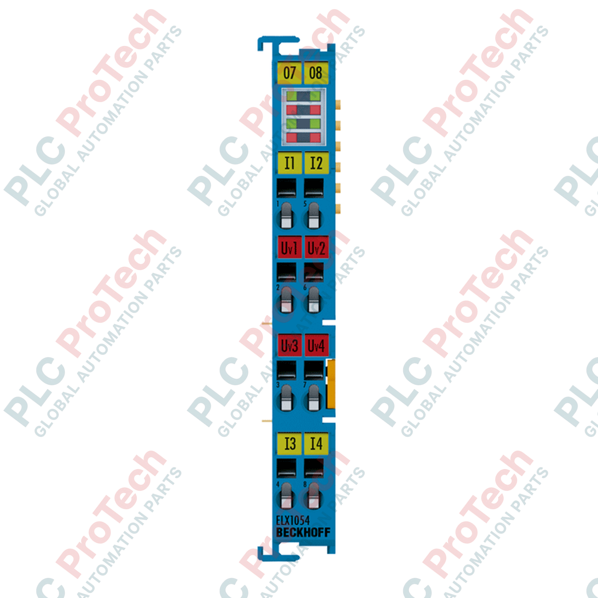
Designed for intrinsically safe signal acquisition in hazardous environments, the Beckhoff ELX1054 enables direct connection of up to four NAMUR field sensors located in Zone 0 or Zone 20. This compact EtherCAT terminal integrates high-density electrical isolation and comprehensive diagnostic features, allowing process automation plants to transmit field signals to the control level without additional external barriers. By combining intrinsically safe inputs and EtherCAT communication in a single 12 mm housing, it minimizes DIN rail space requirements and simplifies Ex-protection loop design.
| Parameter | Specification |
|---|---|
| Manufacturer | Beckhoff |
| Model | ELX1054 |
| Technology | Digital Input (Intrinsically Safe, Ex i) |
| Specification Standard | NAMUR (IEC 60947-5-6) |
| Number of Inputs | 4 |
| Connection Method | 2-wire |
| Open Circuit Voltage | typ. 8.2 V DC |
| "0" Signal Current | <= 1.2 mA |
| "1" Signal Current | >= 2.1 mA |
| Switching Hysteresis | typ. 200 uA |
| Short-Circuit Current | typ. 7 mA |
| Fault Detection Limits | I <= 200 uA (cable break), I >= 6.3 mA (short circuit) |
| Max. Switching Frequency | typ. 5 kHz (duty factor 50%) |
| E-Bus Current Consumption | typ. 70 mA |
| Power Contact Current Consumption | typ. 15 mA + load |
| Supply Voltage Electronics | 24 V DC (via power contacts from ELX9560 power supply) |
| Operating Temperature | -25 to +60 degC |
| Storage Temperature | -40 to +85 degC |
| Relative Humidity | 95%, no condensation |
| Vibration/Shock Resistance | Conforms to EN 60068-2-6 / EN 60068-2-27 |
| EMC Immunity/Emission | Conforms to EN 61000-6-2 / EN 61000-6-4 |
| Material | Polycarbonate |
| Dimensions (W x H x D) | 12 mm x 100 mm x 68 mm |
| Shipping Weight (Calculated) | 0.15 kg (Net weight: 55 g) |
| Package Dimensions (Calculated) | 150 mm x 120 mm x 40 mm |
| Ex Markings |
ATEX: II 3(1)G Ex ec [ia Ga] IIC T4 Gc, II (1)D [Ex ia Da] IIIC, I (M1) [Ex ia Ma] I IECEx: Ex ec [ia Ga] IIC T4 Gc, [Ex ia Da] IIIC, [Ex ia Ma] I cFMus: AIS Class I, II, III, Div 1, Groups A-G; Class I, Div 2, Groups A-D; Class I, Zone 2, AEx ec [ia Ga] IIC T4 Gc |
| Terminal Connection | Signal Assignment |
|---|---|
| Input 1 (Ex i) | Terminal 1 (+), Terminal 5 (-) |
| Input 2 (Ex i) | Terminal 2 (+), Terminal 6 (-) |
| Input 3 (Ex i) | Terminal 3 (+), Terminal 7 (-) |
| Input 4 (Ex i) | Terminal 4 (+), Terminal 8 (-) |
The ELX1054 is exclusively intended for applications requiring intrinsically safe (Ex i) signal processing. For standard (non-hazardous) applications, the Beckhoff EL1054 or EL1004/EL1008 can be used instead. Note that the ELX series must be fed using the specialized ELX9560 power supply terminal to ensure compliance with the required safety barriers and intrinsic safety standards. Mixing Ex i and non-Ex i modules on the same segment without the appropriate separation barriers (such as the ELX9012 distance terminal) is strictly forbidden.
When designing your loop, always ensure that the maximum inductance (Lo) and capacitance (Co) calculations match the Ex-certified values of your NAMUR sensors. Thermal buildup can occur when placing multiple high-density Ex i modules side-by-side. Maintain standard 50 mm clearance above and below the terminal block to allow convection cooling. Failure to supply 24 V DC through the ELX9560 power contacts will cause diagnostic faults on the TwinCAT system, reporting standard E-bus power failure or field-side undervoltage.
For wiring connection, use the spring-clamp terminals with standard 2-wire shielded twisted-pair cables. Strip insulation exactly 8 to 9 mm. Ensure that you do not mix the positive and negative terminals of the NAMUR loops, as this can trigger false cable break alarms (current below 200 uA). In TwinCAT 3, use the standard process data objects (PDOs) to monitor status bits for cable break and short circuit diagnostic errors per channel to enable rapid remote troubleshooting.
Mount the ELX9560 Ex-power supply terminal onto the 35 mm DIN rail to establish safe power contacts.
Slide the ELX1054 terminal into position along the rail guide, engaging the side-by-side double slot and key connection securely.
Using a standard flat-head screwdriver, depress the spring-actuation mechanism, insert the stripped NAMUR sensor wires, and release to lock.
Establish the correct separation distances between the Ex i intrinsic safety wiring and standard non-intrinsically safe cabling inside the cabinet trunking.
| Product Image | Model Number / Title | Condition | Availability | Action |
|---|---|---|---|---|
|
Allen-Bradley 1756-IH16I ControlLogix Digital Input Module | Original New | In Stock | View Details |
Global Express Shipping
Returns & Warranty
Orders are processed and delivered Monday-Friday (excluding public holidays).
For full eligibility, restocking fees, and international return details, please view our official Refund & Return Policy .
| Country of origin |
Germany
|

Implement a 3-SPST switch XOR light circuit in LogixPro or RSLogix 500 using an internal relay bit. Includes truth tables, boolean equations, and verified.

Integrate Allen-Bradley CompactLogix, Caterpillar ATS, and generators into DeltaV DCS over Modbus RTU. Covers ProSoft MVI69-MCM, Miille DIN266 gateways.

ONS instruction fires but the OTE coil never latches in Studio 5000 because the one-shot is only true for one scan. Use OTL/OTU or seal-in logic instead.

Configure Allen-Bradley Kinetix 5500 servo drives on EtherNet/IP. Covers CIP Sync, IEEE 1588 V2 timing, Stratix selection, DLR topology, and HMI.

A moving-average filter is the sliding-window smoother most instrument engineers drop into DCS and PLC analog paths. Here is how the window works, how N and sample time set lag, and when a...

On Frame 5–9 gas turbines, GE Mark VI and Mark VIe run control as function-block application software. This article maps process, protection, and sequencing functions—and what Toolbox ST access...