


Implementing 3-Switch XOR Ladder Logic with Internal Bit
Implement a 3-SPST switch XOR light circuit in LogixPro or RSLogix 500 using an internal relay bit. Includes truth tables, boolean equations, and verified.

Delivering localized output actuation in demanding machine environments, the Beckhoff IP2021-B810 Fieldbus Box integrates serial communications directly at the machine level. This rugged fieldbus module features 8 digital outputs operating at 24 V DC, capable of handling switching currents up to 2 A per channel. Designed for decentralized control systems, the Beckhoff IP2021-B810 processes control signals from a master device over an integrated RS232 serial connection, eliminating the need for complex intermediate sub-distribution assemblies. Its robust construction makes it ideal for direct mounting on machinery under challenging physical conditions.
| Parameter | Specification Value |
|---|---|
| Manufacturer | Beckhoff Automation GmbH & Co. KG |
| Model / Article Number | IP2021-B810 |
| Module Type | Fieldbus Box Digital Output Module |
| Number of Outputs | 8 channels |
| Output Type | Digital, 24 V DC |
| Max. Output Current | 2 A per channel (short-circuit protected) |
| Communication Interface | RS232 serial interface |
| Connection Method | M8 screw-type connectors |
| Ingress Protection Rating | IP67 (when all ports are fully mated or capped) |
| Operating Temperature | 0 to +55 degC |
| Storage Temperature | -25 to +85 degC |
| Shipping Weight (Calculated) | 2.0 kg |
| Package Dimensions (Calculated) | 150 mm x 60 mm x 50 mm |
| M8 Output Pin | Signal Assignment | Description |
|---|---|---|
| Pin 1 | +24 V DC | Auxiliary power / sensor supply contact |
| Pin 3 | GND (0 V) | Reference ground potential |
| Pin 4 | Output Signal | Controlled digital output driver path (24 V DC, 2 A) |
The IP2021-B810 is ideal for localized RS232 architectures. If migration to industrial Ethernet is required, a transition to Beckhoff EP2008 (EtherCAT) or equivalent fieldbus couplers will necessitate replacing the physical M8 cabling with Industrial Ethernet-capable interfaces and adjusting the twinCAT configuration files from serial mappings to standard EtherCAT PDOs.
While each channel supports a high peak capacity of 2 A, the cumulative load current of all channels combined must not exceed the physical capability of the main auxiliary power input pin. Operating all 8 channels simultaneously at maximum load without active thermal management or duty cycling will result in localized thermal buildup and may trigger internal overcurrent protection circuits.
Because RS232 relies on single-ended signals, it is inherently susceptible to electrical noise. Standard engineering rules limit RS232 cable lengths to 15 meters. Ensure the RS232 communication cable is completely shielded, and tie the shield braid to low-impedance ground at the controller end. Do not run communication lines parallel to high-voltage AC or variable frequency drive (VFD) output motor cables.
Always isolate the auxiliary power supply and fieldbus control line before starting maintenance or hardware integration. Electrical arc flashes or accidental grounding of the 2 A output lines can cause severe equipment damage and disrupt controller operations across the wider serial loop.
Mount the Fieldbus Box onto a flat, vibration-damped structural surface using M4 or M5 mounting screws. Torque to the specified mechanical limits to prevent frame distortion.
Connect the RS232 interface cable to the dedicated serial communication port, ensuring the locking ring on the connector is secured to maintain IP67 integrity.
Verify wiring assignments on the M8 output channels to prevent accidental short circuits, and apply protective cap seals over any unused physical ports.
Global Express Shipping
Returns & Warranty


Manufacturer: BECKHOFF
Product No.: IP2021-B810
Country of origin:Germany
Product Type: Fieldbus Box Modules
Payment: T/T, Western Union
Weight: 2000g
Dimensions: 150 mm x 60 mm x 50 mm
Shipping port: Xiamen
Warranty: 12 months
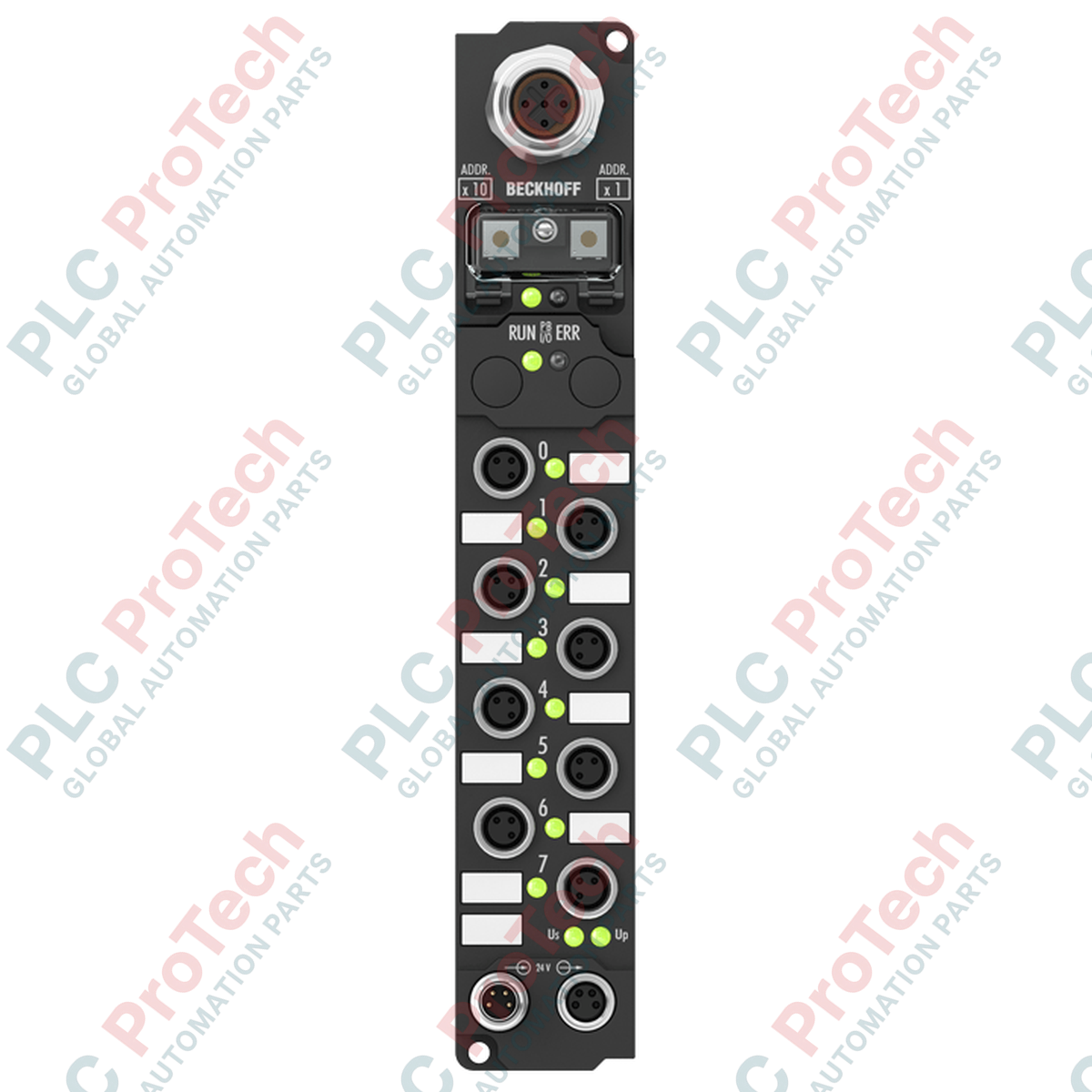
Delivering localized output actuation in demanding machine environments, the Beckhoff IP2021-B810 Fieldbus Box integrates serial communications directly at the machine level. This rugged fieldbus module features 8 digital outputs operating at 24 V DC, capable of handling switching currents up to 2 A per channel. Designed for decentralized control systems, the Beckhoff IP2021-B810 processes control signals from a master device over an integrated RS232 serial connection, eliminating the need for complex intermediate sub-distribution assemblies. Its robust construction makes it ideal for direct mounting on machinery under challenging physical conditions.
| Parameter | Specification Value |
|---|---|
| Manufacturer | Beckhoff Automation GmbH & Co. KG |
| Model / Article Number | IP2021-B810 |
| Module Type | Fieldbus Box Digital Output Module |
| Number of Outputs | 8 channels |
| Output Type | Digital, 24 V DC |
| Max. Output Current | 2 A per channel (short-circuit protected) |
| Communication Interface | RS232 serial interface |
| Connection Method | M8 screw-type connectors |
| Ingress Protection Rating | IP67 (when all ports are fully mated or capped) |
| Operating Temperature | 0 to +55 degC |
| Storage Temperature | -25 to +85 degC |
| Shipping Weight (Calculated) | 2.0 kg |
| Package Dimensions (Calculated) | 150 mm x 60 mm x 50 mm |
| M8 Output Pin | Signal Assignment | Description |
|---|---|---|
| Pin 1 | +24 V DC | Auxiliary power / sensor supply contact |
| Pin 3 | GND (0 V) | Reference ground potential |
| Pin 4 | Output Signal | Controlled digital output driver path (24 V DC, 2 A) |
The IP2021-B810 is ideal for localized RS232 architectures. If migration to industrial Ethernet is required, a transition to Beckhoff EP2008 (EtherCAT) or equivalent fieldbus couplers will necessitate replacing the physical M8 cabling with Industrial Ethernet-capable interfaces and adjusting the twinCAT configuration files from serial mappings to standard EtherCAT PDOs.
While each channel supports a high peak capacity of 2 A, the cumulative load current of all channels combined must not exceed the physical capability of the main auxiliary power input pin. Operating all 8 channels simultaneously at maximum load without active thermal management or duty cycling will result in localized thermal buildup and may trigger internal overcurrent protection circuits.
Because RS232 relies on single-ended signals, it is inherently susceptible to electrical noise. Standard engineering rules limit RS232 cable lengths to 15 meters. Ensure the RS232 communication cable is completely shielded, and tie the shield braid to low-impedance ground at the controller end. Do not run communication lines parallel to high-voltage AC or variable frequency drive (VFD) output motor cables.
Always isolate the auxiliary power supply and fieldbus control line before starting maintenance or hardware integration. Electrical arc flashes or accidental grounding of the 2 A output lines can cause severe equipment damage and disrupt controller operations across the wider serial loop.
Mount the Fieldbus Box onto a flat, vibration-damped structural surface using M4 or M5 mounting screws. Torque to the specified mechanical limits to prevent frame distortion.
Connect the RS232 interface cable to the dedicated serial communication port, ensuring the locking ring on the connector is secured to maintain IP67 integrity.
Verify wiring assignments on the M8 output channels to prevent accidental short circuits, and apply protective cap seals over any unused physical ports.
Global Express Shipping
Returns & Warranty
Orders are processed and delivered Monday-Friday (excluding public holidays).
For full eligibility, restocking fees, and international return details, please view our official Refund & Return Policy .
| Country of origin |
Germany
|

Implement a 3-SPST switch XOR light circuit in LogixPro or RSLogix 500 using an internal relay bit. Includes truth tables, boolean equations, and verified.

Integrate Allen-Bradley CompactLogix, Caterpillar ATS, and generators into DeltaV DCS over Modbus RTU. Covers ProSoft MVI69-MCM, Miille DIN266 gateways.

ONS instruction fires but the OTE coil never latches in Studio 5000 because the one-shot is only true for one scan. Use OTL/OTU or seal-in logic instead.

Configure Allen-Bradley Kinetix 5500 servo drives on EtherNet/IP. Covers CIP Sync, IEEE 1588 V2 timing, Stratix selection, DLR topology, and HMI.

A moving-average filter is the sliding-window smoother most instrument engineers drop into DCS and PLC analog paths. Here is how the window works, how N and sample time set lag, and when a...

On Frame 5–9 gas turbines, GE Mark VI and Mark VIe run control as function-block application software. This article maps process, protection, and sequencing functions—and what Toolbox ST access...