


Implementing 3-Switch XOR Ladder Logic with Internal Bit
Implement a 3-SPST switch XOR light circuit in LogixPro or RSLogix 500 using an internal relay bit. Includes truth tables, boolean equations, and verified.

Designed to optimize decentralized control layouts, this Beckhoff IP2042-B528 digital output module enables high-capacity load switching directly on-machine via a DeviceNet fieldbus interface. By shifting the I/O layer out of the central control cabinet and directly onto the equipment frame, it minimizes wiring overhead and reduces signal degradation. The module features eight independent digital outputs designed to switch 24 V DC loads up to 2 A per channel, utilizing standard M12 screw-locking connectors to guarantee reliable signal delivery under harsh operating conditions.
| Parameter | Specification |
|---|---|
| Manufacturer | Beckhoff |
| Model Number | IP2042-B528 |
| Fieldbus Interface | DeviceNet (with integrated T-connector) |
| Number of Channels | 8 digital outputs |
| Nominal Output Voltage | 24 V DC |
| Max. Output Current (Per Channel) | 2 A |
| Max. Cumulative Current (Total Module) | 12 A |
| Connection Type | M12 screw-locking connector |
| Operating Temperature Range | 0 to 55 degC |
| Storage Temperature Range | -25 to 85 degC |
| Country of Origin | Germany |
| Shipping Weight (Calculated) | 0.45 kg |
| Package Dimensions (Calculated) | 180 mm x 80 mm x 50 mm |
This module uses the B528 DeviceNet interface suffix. It is not a direct drop-in network replacement for other Fieldbus Box versions such as the B510 (CANopen) or B310 (PROFIBUS), as these require completely different configuration files (EDS vs. GSD) and master scanners. Always ensure the network scanner in your PLC or industrial PC supports DeviceNet communications before swapping modules.
While individual channels can drive up to 2 A, the cumulative current limit for the entire module is strictly rated at 12 A. Running all eight channels at a continuous 2 A simultaneously will draw 16 A, violating the thermal threshold of the internal busbar. To prevent premature module failure, implement duty-cycle management or software-based interlocks to ensure the active current load does not exceed 12 A under continuous operation.
The integrated T-connector is highly convenient for daisy-chaining, but it does not remove the requirement for termination. Make sure that the final module on your physical DeviceNet trunk line is fitted with a standard 121-ohm termination resistor. To guard against noise induced by nearby variable frequency drives (VFDs), ensure that the M12 fieldbus cables have their shields securely grounded to the machine bed through the module's metal mounting tabs.
Isolate and lock out all 24 V DC auxiliary and fieldbus power supplies before attempting installation, wiring, or removal. Plugging or unplugging active M12 connectors under load can lead to electrical contact degradation, unpredictable safety output states, or damage to internal switching components.
Global Express Shipping
Returns & Warranty


Manufacturer: BECKHOFF
Product No.: IP2042-B528
Country of origin:Germany
Product Type: Fieldbus Box Modules
Payment: T/T, Western Union
Weight: 2000g
Dimensions: 180 mm x 80 mm x 50 mm
Shipping port: Xiamen
Warranty: 12 months
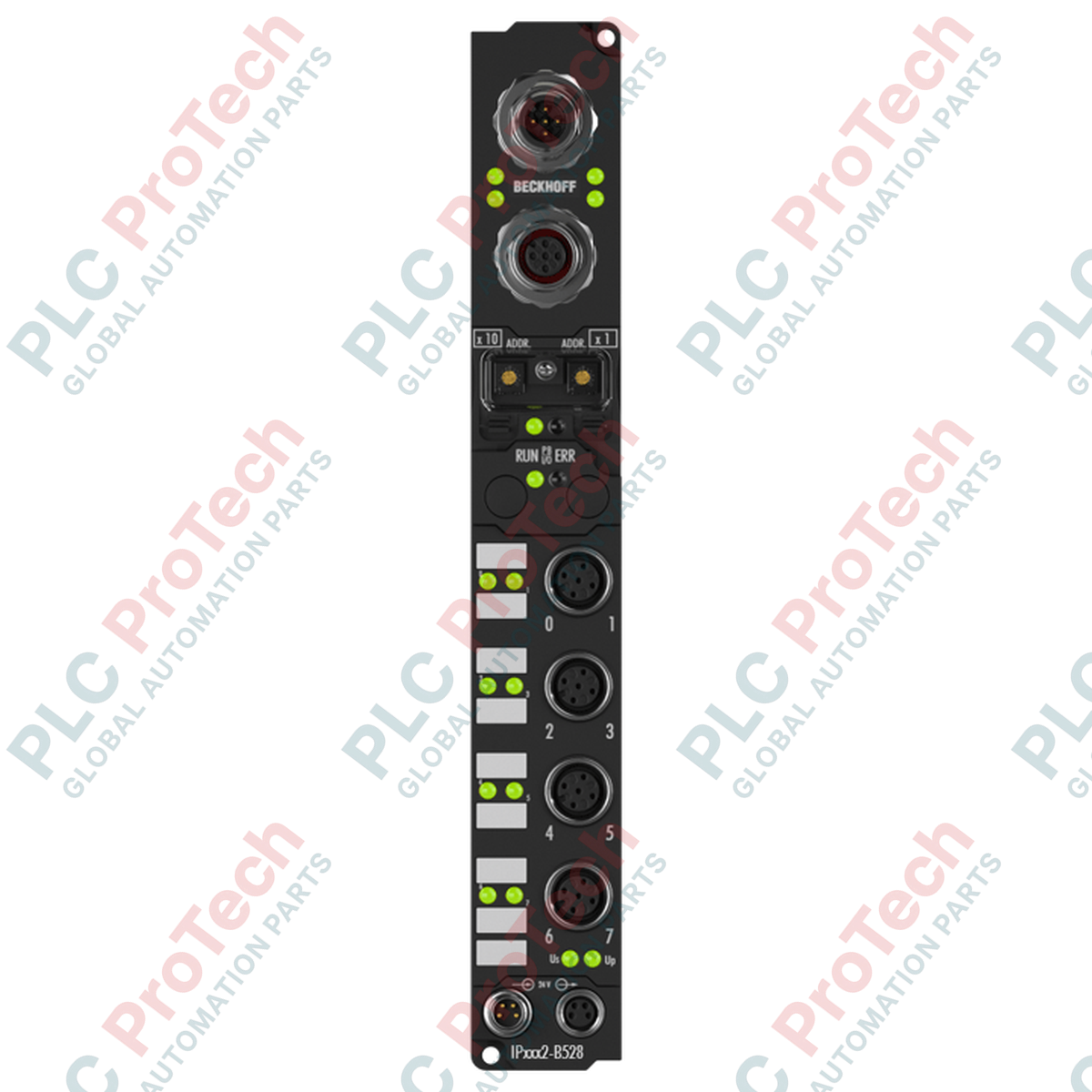
Designed to optimize decentralized control layouts, this Beckhoff IP2042-B528 digital output module enables high-capacity load switching directly on-machine via a DeviceNet fieldbus interface. By shifting the I/O layer out of the central control cabinet and directly onto the equipment frame, it minimizes wiring overhead and reduces signal degradation. The module features eight independent digital outputs designed to switch 24 V DC loads up to 2 A per channel, utilizing standard M12 screw-locking connectors to guarantee reliable signal delivery under harsh operating conditions.
| Parameter | Specification |
|---|---|
| Manufacturer | Beckhoff |
| Model Number | IP2042-B528 |
| Fieldbus Interface | DeviceNet (with integrated T-connector) |
| Number of Channels | 8 digital outputs |
| Nominal Output Voltage | 24 V DC |
| Max. Output Current (Per Channel) | 2 A |
| Max. Cumulative Current (Total Module) | 12 A |
| Connection Type | M12 screw-locking connector |
| Operating Temperature Range | 0 to 55 degC |
| Storage Temperature Range | -25 to 85 degC |
| Country of Origin | Germany |
| Shipping Weight (Calculated) | 0.45 kg |
| Package Dimensions (Calculated) | 180 mm x 80 mm x 50 mm |
This module uses the B528 DeviceNet interface suffix. It is not a direct drop-in network replacement for other Fieldbus Box versions such as the B510 (CANopen) or B310 (PROFIBUS), as these require completely different configuration files (EDS vs. GSD) and master scanners. Always ensure the network scanner in your PLC or industrial PC supports DeviceNet communications before swapping modules.
While individual channels can drive up to 2 A, the cumulative current limit for the entire module is strictly rated at 12 A. Running all eight channels at a continuous 2 A simultaneously will draw 16 A, violating the thermal threshold of the internal busbar. To prevent premature module failure, implement duty-cycle management or software-based interlocks to ensure the active current load does not exceed 12 A under continuous operation.
The integrated T-connector is highly convenient for daisy-chaining, but it does not remove the requirement for termination. Make sure that the final module on your physical DeviceNet trunk line is fitted with a standard 121-ohm termination resistor. To guard against noise induced by nearby variable frequency drives (VFDs), ensure that the M12 fieldbus cables have their shields securely grounded to the machine bed through the module's metal mounting tabs.
Isolate and lock out all 24 V DC auxiliary and fieldbus power supplies before attempting installation, wiring, or removal. Plugging or unplugging active M12 connectors under load can lead to electrical contact degradation, unpredictable safety output states, or damage to internal switching components.
Global Express Shipping
Returns & Warranty
Orders are processed and delivered Monday-Friday (excluding public holidays).
For full eligibility, restocking fees, and international return details, please view our official Refund & Return Policy .
| Country of origin |
Germany
|

Implement a 3-SPST switch XOR light circuit in LogixPro or RSLogix 500 using an internal relay bit. Includes truth tables, boolean equations, and verified.

Integrate Allen-Bradley CompactLogix, Caterpillar ATS, and generators into DeltaV DCS over Modbus RTU. Covers ProSoft MVI69-MCM, Miille DIN266 gateways.

ONS instruction fires but the OTE coil never latches in Studio 5000 because the one-shot is only true for one scan. Use OTL/OTU or seal-in logic instead.

Configure Allen-Bradley Kinetix 5500 servo drives on EtherNet/IP. Covers CIP Sync, IEEE 1588 V2 timing, Stratix selection, DLR topology, and HMI.

A moving-average filter is the sliding-window smoother most instrument engineers drop into DCS and PLC analog paths. Here is how the window works, how N and sample time set lag, and when a...

On Frame 5–9 gas turbines, GE Mark VI and Mark VIe run control as function-block application software. This article maps process, protection, and sequencing functions—and what Toolbox ST access...