


Implementing 3-Switch XOR Ladder Logic with Internal Bit
Implement a 3-SPST switch XOR light circuit in LogixPro or RSLogix 500 using an internal relay bit. Includes truth tables, boolean equations, and verified.

Decentralized signal acquisition on the factory floor is handled efficiently by the Beckhoff IP2310-B310 Fieldbus Box. This robust distributed I/O module integrates 4 digital inputs and 4 digital outputs directly into a high-speed PROFIBUS DP network without requiring an IP20 protective enclosure. Designed for direct machine-mounting, the device processes rapid digital signals with a 0.2 ms filter constant while offering high protection against environmental moisture and particulates. The Beckhoff IP2310-B310 enables engineers to minimize control cabinet space and drastically reduce field-level wiring complexity by mounting the control interfaces directly on the mechanical structure.
| Parameter | Specification |
|---|---|
| Manufacturer | BECKHOFF |
| Model Code | IP2310-B310 |
| Fieldbus System | PROFIBUS DP |
| Digital Inputs | 4 x 24 V DC (Filter: 0.2 ms) |
| Digital Outputs | 4 x 24 V DC (0.5 A per channel, short-circuit proof) |
| Control Voltage | 24 V DC (-15% / +20%) |
| Sensor Supply Current | Max. 0.5 A sum total for all sensors |
| I/O Connection Method | M8 (dia 8 mm) screw-lock / snap-in connectors |
| Operating Temperature | 0 degC to +55 degC |
| Storage Temperature | -25 degC to +85 degC |
| Protection Class | IP67 |
| Country of Origin | Germany |
| Shipping Weight (Calculated) | 2.0 kg |
| M8 Connector Pin | Input Port Function | Output Port Function |
|---|---|---|
| Pin 1 | +24 V DC Sensor Supply | Not Connected / Reserve |
| Pin 3 | GND (0 V) | GND (0 V) |
| Pin 4 | Input Signal (Ch 1 - 4) | Output Signal (Ch 1 - 4) |
When migrating legacy systems, note that the IP2310-B310 uses the PROFIBUS DP standard protocol and relies on specific GSD files (typically I2310B31.gsd) during PLC hardware configuration. If replacing this module with newer EtherCAT-based options like the EP2318-0001, complete changes to the master controller configuration and physical cabling infrastructure are mandatory.
Although the output channels are short-circuit protected and rated for 0.5 A each, the total combined current of the module's sensor supplies must not exceed 0.5 A. Deploying multiple high-draw photo-eye sensors without supplementary external distribution blocks will trip the internal thermal fuses. Ensure inductive load suppression (e.g., flyback diodes) is integrated externally when driving high-inductance pneumatic solenoids to prevent premature degradation of the solid-state output circuitry.
For robust PROFIBUS communication at rates exceeding 1.5 Mbaud, ensure that both physical ends of the PROFIBUS segment are properly terminated with active 220-ohm pull-up termination resistors. Keep the standard M8 sensor lines under 3 meters to prevent inductive coupling and high-frequency noise interference from adjacent variable frequency drive (VFD) cables.
CRITICAL SAFETY WARNING
Before starting physical mounting, wiring, or maintenance on the PROFIBUS network, isolate all electrical power supplies. Disconnect both the control power (Us) and peripheral load power (Up) channels. Failure to de-energize can lead to accidental actuator actuation or severe communication dropouts due to transient ground loops.
Position the module flat against a clean, vibration-resistant machine frame structure. Securely tighten both mounting screws (M4 size) using an appropriate torque limit of 1.2 Nm to guarantee mechanical grounding.
Connect the incoming PROFIBUS and local power distribution cabling. Verify that all unused M12 and M8 connector sockets are sealed with official IP67 protective caps to keep out environmental moisture.
Adjust the rotary hardware address switches on the front face of the module to align exactly with the assigned node address configured inside your central PLC hardware configuration tool.
Global Express Shipping
Returns & Warranty


Manufacturer: BECKHOFF
Product No.: IP2310-B310
Country of origin:Germany
Product Type: Distributed I/O Modules
Payment: T/T, Western Union
Weight: 2000g
Shipping port: Xiamen
Warranty: 12 months
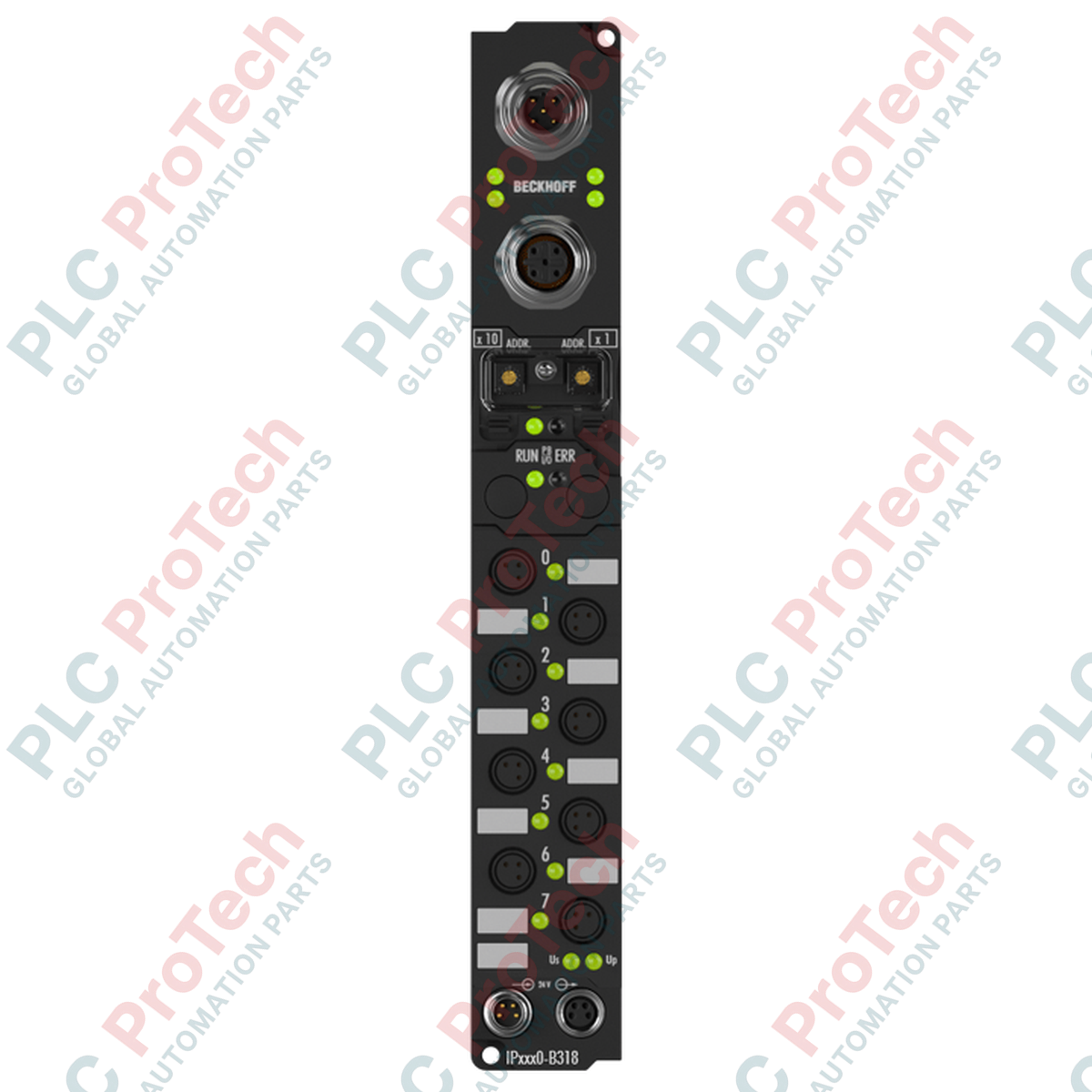
Decentralized signal acquisition on the factory floor is handled efficiently by the Beckhoff IP2310-B310 Fieldbus Box. This robust distributed I/O module integrates 4 digital inputs and 4 digital outputs directly into a high-speed PROFIBUS DP network without requiring an IP20 protective enclosure. Designed for direct machine-mounting, the device processes rapid digital signals with a 0.2 ms filter constant while offering high protection against environmental moisture and particulates. The Beckhoff IP2310-B310 enables engineers to minimize control cabinet space and drastically reduce field-level wiring complexity by mounting the control interfaces directly on the mechanical structure.
| Parameter | Specification |
|---|---|
| Manufacturer | BECKHOFF |
| Model Code | IP2310-B310 |
| Fieldbus System | PROFIBUS DP |
| Digital Inputs | 4 x 24 V DC (Filter: 0.2 ms) |
| Digital Outputs | 4 x 24 V DC (0.5 A per channel, short-circuit proof) |
| Control Voltage | 24 V DC (-15% / +20%) |
| Sensor Supply Current | Max. 0.5 A sum total for all sensors |
| I/O Connection Method | M8 (dia 8 mm) screw-lock / snap-in connectors |
| Operating Temperature | 0 degC to +55 degC |
| Storage Temperature | -25 degC to +85 degC |
| Protection Class | IP67 |
| Country of Origin | Germany |
| Shipping Weight (Calculated) | 2.0 kg |
| M8 Connector Pin | Input Port Function | Output Port Function |
|---|---|---|
| Pin 1 | +24 V DC Sensor Supply | Not Connected / Reserve |
| Pin 3 | GND (0 V) | GND (0 V) |
| Pin 4 | Input Signal (Ch 1 - 4) | Output Signal (Ch 1 - 4) |
When migrating legacy systems, note that the IP2310-B310 uses the PROFIBUS DP standard protocol and relies on specific GSD files (typically I2310B31.gsd) during PLC hardware configuration. If replacing this module with newer EtherCAT-based options like the EP2318-0001, complete changes to the master controller configuration and physical cabling infrastructure are mandatory.
Although the output channels are short-circuit protected and rated for 0.5 A each, the total combined current of the module's sensor supplies must not exceed 0.5 A. Deploying multiple high-draw photo-eye sensors without supplementary external distribution blocks will trip the internal thermal fuses. Ensure inductive load suppression (e.g., flyback diodes) is integrated externally when driving high-inductance pneumatic solenoids to prevent premature degradation of the solid-state output circuitry.
For robust PROFIBUS communication at rates exceeding 1.5 Mbaud, ensure that both physical ends of the PROFIBUS segment are properly terminated with active 220-ohm pull-up termination resistors. Keep the standard M8 sensor lines under 3 meters to prevent inductive coupling and high-frequency noise interference from adjacent variable frequency drive (VFD) cables.
CRITICAL SAFETY WARNING
Before starting physical mounting, wiring, or maintenance on the PROFIBUS network, isolate all electrical power supplies. Disconnect both the control power (Us) and peripheral load power (Up) channels. Failure to de-energize can lead to accidental actuator actuation or severe communication dropouts due to transient ground loops.
Position the module flat against a clean, vibration-resistant machine frame structure. Securely tighten both mounting screws (M4 size) using an appropriate torque limit of 1.2 Nm to guarantee mechanical grounding.
Connect the incoming PROFIBUS and local power distribution cabling. Verify that all unused M12 and M8 connector sockets are sealed with official IP67 protective caps to keep out environmental moisture.
Adjust the rotary hardware address switches on the front face of the module to align exactly with the assigned node address configured inside your central PLC hardware configuration tool.
Global Express Shipping
Returns & Warranty
Orders are processed and delivered Monday-Friday (excluding public holidays).
For full eligibility, restocking fees, and international return details, please view our official Refund & Return Policy .
| Country of origin |
Germany
|

Implement a 3-SPST switch XOR light circuit in LogixPro or RSLogix 500 using an internal relay bit. Includes truth tables, boolean equations, and verified.

Integrate Allen-Bradley CompactLogix, Caterpillar ATS, and generators into DeltaV DCS over Modbus RTU. Covers ProSoft MVI69-MCM, Miille DIN266 gateways.

ONS instruction fires but the OTE coil never latches in Studio 5000 because the one-shot is only true for one scan. Use OTL/OTU or seal-in logic instead.

Configure Allen-Bradley Kinetix 5500 servo drives on EtherNet/IP. Covers CIP Sync, IEEE 1588 V2 timing, Stratix selection, DLR topology, and HMI.

A moving-average filter is the sliding-window smoother most instrument engineers drop into DCS and PLC analog paths. Here is how the window works, how N and sample time set lag, and when a...

On Frame 5–9 gas turbines, GE Mark VI and Mark VIe run control as function-block application software. This article maps process, protection, and sequencing functions—and what Toolbox ST access...