High-Density System Infrastructure
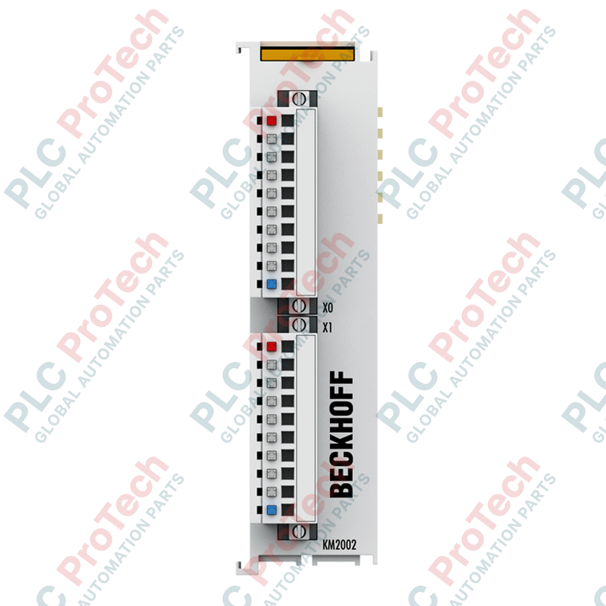
The Beckhoff KM2002-0000 (KM2002-0000) is a high-density 16-channel digital output Bus Terminal module engineered within Beckhoff’s compact form-factor I/O ecosystem. Deployed across space-constrained control enclosures, high-throughput packaging lines, electronic assembly machines, and centralized sorting systems, this module acts as a bridge between the digital processing layer and field-level actuators. By packaging 16 independent output channels into a single 26.5 mm wide module layout, the hardware maximizes I/O footprint efficiency inside electrical control cabinets while interfacing directly with standard K-bus backplane networks.
Electrical Isolation and Solid-State Switching Architecture
The module distributes its 16 binary control paths across two independent pluggable terminal blocks, with each connector block driving an 8-channel matrix. Built with solid-state switches designed to transition 24 VDC potentials, each output channel delivers a continuous rated current capacity of 0.5 A. The module incorporates complete 500 V galvanic electrical isolation between the internal K-bus logic components and the external field potential, protecting sensitive upstream processor circuitry from industrial transient spikes. Each solid-state output is short-circuit proof, features built-in reverse voltage protection, and handles inductive inductive energy dissipation limits below 150 mJ per channel.
Technical Performance Matrix
| Core Parameter |
Functional Specification |
| Model Variant |
KM2002-0000 (Base module supplied without pluggable connectors) |
| Brand / Product Family |
Beckhoff Automation / High-Density Compact Terminal Modules |
| Output Density |
16 digital outputs (Structured as 2 x 8-channel zones) |
| Nominal Operating Potential |
24 VDC |
| Max Continuous Load Current |
0.5 A per channel (Fully short-circuit proof) |
| Peak Short-Circuit Threshold |
< 2 A |
| Inductive Demagnetization Energy |
< 150 mJ per channel maximum breaking energy |
| Galvanic Isolation |
500 V (Internal K-bus logic isolated from external field potential) |
| Reverse Voltage Safeguard |
Integrated inside power switching stage |
| Logic-Side Current Demand |
Typically 5 mA drawn from K-bus rail |
| Process Image Allocation |
16 digital outputs (16 bits total width) |
| Mechanical Dimensions (W x H x D) |
26.5 mm x 100 mm x 71 mm |
| Net Structural Weight |
approx. 90 g (Base module weight without wiring plug blocks) |
| Shipping Gross Weight |
2.0 kg (Enclosed in large-lot industrial packaging) |
Module Family Matrix
| Model Extension |
Wiring Format Interface |
Status Indicator Features |
| KM2002-0000 |
Supplied without plug-in wiring block inserts |
Main module base only |
| KM2002-0001 |
Includes standard 1-wire pluggable connectors |
No faceplate indicator LEDs |
| KM2002-0002 |
Includes standard 1-wire pluggable connectors |
Integrated channel status diagnostic LEDs |
| KM2002-0004 |
Includes advanced 3-wire pluggable connectors |
Integrated channel status diagnostic LEDs |
Industrial Diagnostics and FAQs
What are the primary troubleshooting steps if multiple adjacent channels drop to 0 V under full load?
A collective channel shutdown indicates either a thermal overload trip or an active short-circuit state. The KM2002-0000 includes internal electronic short-circuit protection that restricts current to less than 2 A under fault conditions. Disconnect the pluggable field wiring connector and measure the resistive load across the failing actuator line. If the line resistance tracks below 48 ohms, locate and fix the shorted field coil or pinched cable before re-seating the connector plug.
Why does this module have a current consumption entry of zero for the power contacts?
The KM2002-0000 base housing does not utilize standard internal lateral power blade contacts to transfer 24 VDC field potential down the DIN rail stack. Instead, the 24 VDC actuator driving potential must be wired directly into the dedicated power supply pins located on the pluggable front wiring connectors to energize the respective 8-channel switching groups.
Can this 0.5 A solid-state channel directly actuate a large Size 3 pneumatic valve manifold?
Yes, provided the continuous holding current of the pneumatic solenoid coil tracks below 0.5 A at 24 VDC (equivalent to a maximum continuous load power rating of 12 W). For large heavy-duty solenoids or mechanical contactor coils whose inrush surges or inductive dissipation spikes approach the 150 mJ breaking energy threshold, install an external flyback diode parallel to the load to prevent premature degradation of the module's solid-state switches.
Field Commissioning and Installation Directives
-
Pluggable Block Alignment and Conductor Termination: When landing field wires, strip individual conductor insulation back exactly 8 mm. The wire clamp mechanism accepts solid or stranded conductors from 0.08 to 1.5 mm². Insert the conductor fully into the terminal point and verify the spring clip captures the wire firmly. When mounting the plug block onto the module face, push it straight in until the mechanical locking ears snap into place.
-
DIN Rail Grounding and Interlocking Stack: Snap the module vertically onto a standard 35 mm TS35 DIN rail. Ensure the double slot-and-key side guides lock securely with adjacent I/O components. Confirm that the DIN rail itself is connected to a low-impedance master enclosure ground plate to allow internal filtering networks to bleed off high-frequency electromagnetic noise.
-
Enclosure Vent Management and Clearance: This high-density module carries an IP20 protection class and must be housed within a clean, moisture-controlled industrial cabinet. Maintain an open clearance path of at least 30 mm above and below the module assembly. If the 16 outputs run concurrently at full 0.5 A loads under high ambient external conditions, ensure active cooling fan ventilation keeps internal cabinet temperatures below the 55 deg C operating limit.