


Troubleshooting Beckhoff KL1512 Counter Inputs and Mapping
A field checklist for KL1512 signal thresholds, counter direction, process data and the KL1512-to-KS1512 wiring difference.
Manufacturer: Bently Nevada
Product No.: 21747-045-00
Country of origin:United States
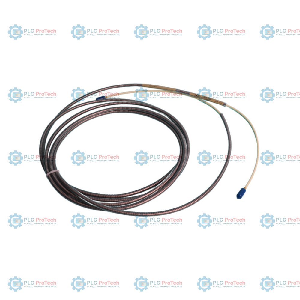
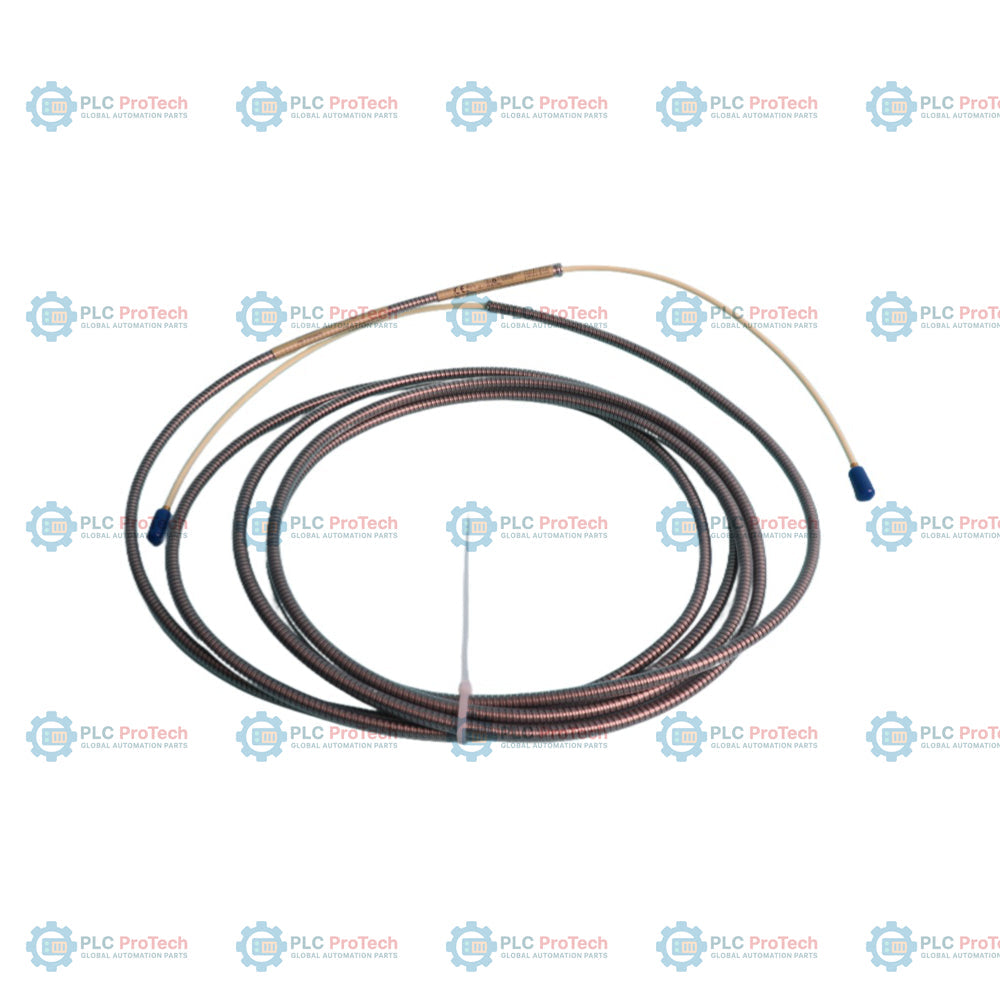
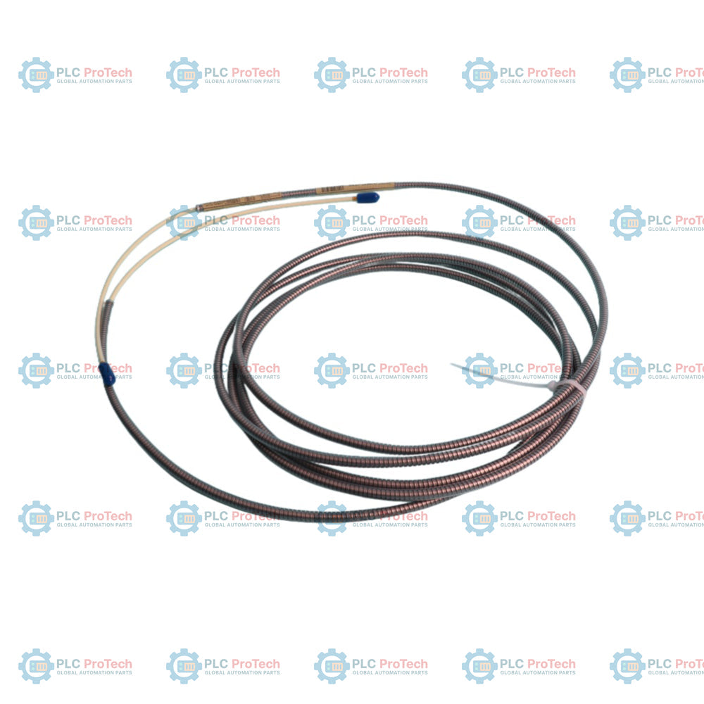
Product Type: Extension Cable
Barcode: 8537101190
Payment: T/T, Western Union
Weight: 80g
Dimensions: 112cm x 1.5cm x 1.2cm
Shipping port: Xiamen
Warranty: 12 months
| Orderable Part Number | 21747-045-00 | 7200 Series Extension Cable |
| Option A - Cable Length | 045 | 4.5 metres (177 inches) |
| Option B - Armor | 00 | Without armor |
| Manufacturer | Bently Nevada |
| Part Number | 21747-045-00 |
| System Series | 7200 Proximity Transducer System |
| Cable Length | 4.5 metres |
| Armor | None |
| Operating Temperature | -34 degC to +177 degC |
| Compatibility | 7200 5 mm and 8 mm Probes and Proximitors |


Global Express Shipping
Returns & Warranty


Global Express Shipping
Returns & Warranty
Orders are processed and delivered Monday-Friday (excluding public holidays).
For full eligibility, restocking fees, and international return details, please view our official Refund & Return Policy .
| Country of origin |
United States
|

A field checklist for KL1512 signal thresholds, counter direction, process data and the KL1512-to-KS1512 wiring difference.

A field checklist for EPP2008-0001 current limits, supply voltage, channel LEDs, connector coding and load-related output faults.

Before moving a TwinCAT 3 license with a Beckhoff C9900-L100, verify the TwinCAT build, XML device description, exact order code and cabinet limits.

A field checklist for replacing a Beckhoff EL4032, covering the ±10 V load, terminal map, power contacts, EtherCAT state, and watchdog behavior.

Before replacing a Yokogawa AAI835, verify the 4-in/4-out channel map, power-loss loop behavior, barrier type, output load, cable, and redundancy.

ABB PM891K01 article 3BSE053241R1 is the non-redundant AC 800M processor kit. Use this field checklist before replacement.