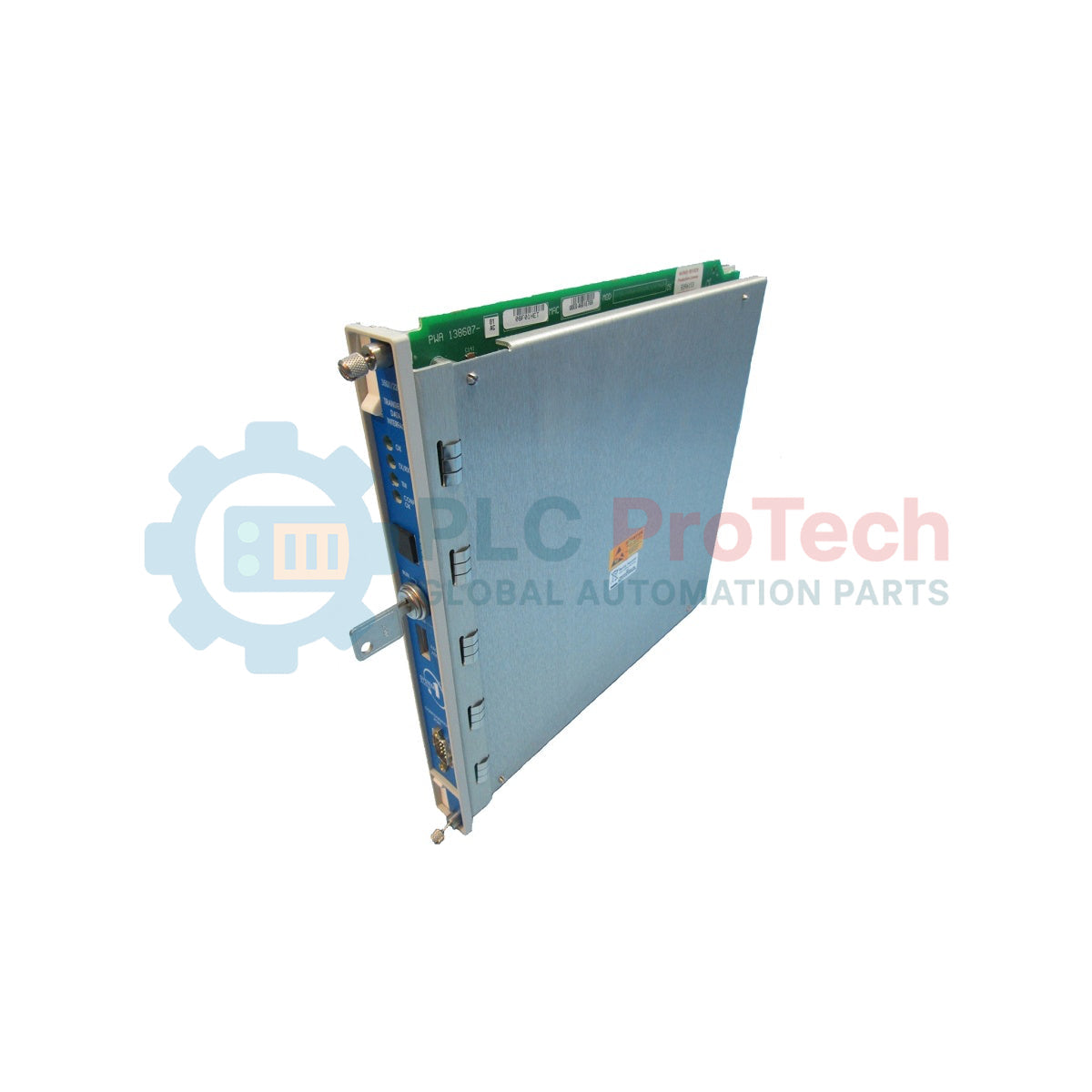
Bently Nevada 3500/22-01-01-02 3500/22M Transient Data Interface Module
SKU 3500/22-01-01-02
In stock
No reviews
12-month warranty
Free returns within 30 days
Manufacturer:
Bently Nevada
Product No.:
3500/22-01-01-02
Country of origin:United States
Product Type:
Transient Data Interfaces
Payment:
T/T, Western Union
Weight:
910g
Dimensions:
241.3 mm x 24.4 mm x 241.8 mm
Shipping port:
Xiamen
Warranty:
12 months
Description
The 3500/22-01-01-02 acts as the core communication and telemetry gateway for the 3500 machinery protection rack. This 3500/22M Transient Data Interface Module establishes a high-speed data path between the physical monitoring chassis and host application suites, including System 1 Condition Monitoring and Diagnostic software alongside dedicated 3500 System Configuration interfaces. By merging the foundational features of a legacy 3500/20 Rack Interface Module (RIM) with the high-bandwidth data handling of an integrated communication processor, the unit supplies streamlined machinery monitoring infrastructure. It interfaces directly with M series monitoring modules inside the backplane to continuously collect stable steady-state parameters and high-density transient dynamic waveform data, streaming this payload over an integrated Ethernet line to host software networks. The module provides standard static data logging capabilities out of the box, with options to support advanced high-resolution wave recording through a supplementary channel enabling license disk. Occupying the dedicated control slot positioned immediately next to the primary rack power supplies, it coordinates global chassis interactions without altering or delaying the independent, safety-critical machine trip paths managed by the individual machinery monitors.
Features
Integrated Communications Framework: Merges standard rack interface module coordination with localized communication processing inside a single slot footprint.
Simultaneous Waveform Telemetry: Captures both synchronous and asynchronous dynamic waveform recordings across up to 48 individual machinery monitoring channels.
Dedicated Data Management: Buffers detailed pre-alarm and post-alarm event states, logging high-density static variables at 100 millisecond sampling windows during sudden threshold infractions.
Multi-Protocol Communications: Embedded processing engines natively execute BN Host Protocol and BN TDI Protocol over standard TCP/IP network structures.
Non-Interfering Safety Architecture: Runs independently from the critical hardware trip pathways to ensure any unexpected network disruption cannot halt machinery shutdown loops.
Hardware Mode Security: Employs a physical front-panel configuration keylock switch to secure operational states against unauthorized remote parameter modification.
Applications
Real-Time Transient Shaft Orbit and Waveform Telemetry Capture during Machine Startup and Coastdown
Machinery Predictive Maintenance and Advanced Condition Diagnostics with System 1 Networks
High-Speed Multichannel Vibration Data Acquisition on Steam Turbines and Turbo-Compressor Trains
Multi-Event Keyphasor Phase Reference Tracking and Timing Management Across the System Rack
Ordering Information
The explicit component configuration breakdowns below match the hardware option parameters for the 3500/22-01-01-02 assembly:
Option Code
Specification
3500/22
Transient Data Interface Module and I/O
01
Standard Transient Data Interface Type (use for standard monitoring applications)
01
10Base-T/100Base-TX Ethernet I/O Module Type
02
Multi Agency Approval (CSA, ATEX, IECEx)
Technical Specifications
Electrical
Parameter
Value
Power Consumption
10.5 Watts
Standard OK Relay Rating
5A @ 24 Vdc / 120 Vac, 120 Watts / 600 VA Switched Power maximum
Relay Contact Design
Arc suppressors provided; operates as Normally Energized
Front Port Communication
USB-B port supporting BN Host Protocol up to 115.2 kbaud maximum
USB Cable Distance
5 meters (16.4 ft) maximum
Rear Port Communication
Ethernet 10Base-T/100Base-TX auto-sensing, conforming to IEEE802.3
Copper Cable Distance
100 meters (328 feet) maximum via RJ-45 connection
Keyphasor Inputs Supported
Four 3500 system Keyphasor signals up to 20 kHz tracking
241.3 mm x 24.4 mm x 241.8 mm (9.50 in x 0.96 in x 9.52 in)
Main Module Weight
0.91 kg (2.0 lbs)
I/O Module Dimensions (H x W x D)
241.3 mm x 24.4 mm x 99.1 mm (9.50 in x 0.96 in x 3.90 in)
I/O Module Weight
0.20 kg (0.44 lbs)
Rack Slot Allocation (Front)
1 full-height front slot (Slot 1 adjacent to power supplies)
Rack Slot Allocation (Rear)
1 full-height rear slot
Environmental
Parameter
Value
Operating Temperature
-30 degC to +65 degC (-22 degF to +149 degF)
Storage Temperature
-40 degC to +85 degC (-40 degF to +185 degF)
Relative Humidity Limit
95%, non-condensing
Powered Internal Battery Life
38 years @ 50 degC (122 degF)
Unpowered Internal Battery Life
12 years @ 50 degC (122 degF)
Connections/Interfaces
The interface connections on the front main processor module and the rear copper 10Base-T/100Base-TX Ethernet I/O module employ the following terminal mappings:
Port/Component Pin
Functional Assignment
Front Panel USB Port
USB-B Configuration Port for local software configuration and programming
Front Panel Keylock Switch
Physical switch selecting RUN mode or PROGRAM mode configuration states
Rear I/O Terminal 7
OK Relay interface indicating the mechanical and internal health status of the rack
Rear I/O Terminal 8
Signal Common external grounding terminal for single point connection
Rear I/O Port 9
RJ-45 Ethernet Port for standard 10Base-T/100Base-TX network cabling links
Rear I/O Terminal 10
System Contact inputs supporting Trip Multiply, Alarm Inhibit, and Rack Reset
Installation Guidelines
Module Slot Placement: The TDI main processor module must be locked into Slot 1 of the 3500 instrument rack, which is the front slot located directly next to the power supply units.
Upgrade Precedence Advisory: When upgrading an existing rack infrastructure from an older 3500/20 RIM module, you must extract the old RIM processor and its companion RIM I/O card before sliding the new TDI components into position. Retaining legacy RIM I/O hardware inside the backplane during TDI power-on will cause immediate, permanent circuit damage to the new TDI module.
Signal Grounding Configuration: To tie the Signal Common line to a single-point instrument ground via the 2-pin connector on the rear I/O module, you must slide the selector switch on the side of the Power Input Module (PIM) toward the arrow marked "HP". This successfully isolates signal common traces from safety chassis grounds.
USB Isolation Caution: The specific USB download cable (part number 123M4610) must be utilized for programming links to sustain total electrical isolation between the rack chassis and reference earth ground. Additionally, ensure the configuration laptop is operating strictly on battery power (completely unplugged from grid mains) to eliminate the risk of introducing ground loop noise.
Compliance and Certifications
FCC: Complies with part 15 of the FCC Rules.
EMC Directive: European Community Directive 2014/30/EU; Standards: EN 61000-6-2 (Industrial Immunity) and EN 61000-6-4 (Industrial Emissions).
Electrical Safety: European Community Low Voltage Directive 2014/35/EU conforming to standard EN 61010-1.
RoHS Directive: Complies with European Community Directive 2011/65/EU.
Maritime Approval: DNV GL rules for classification of ships/offshore units and ABS Rules for Condition of Classification Part 1.
Hazardous Area Approvals: Class I, Division 2, Groups A, B, C, and D; Class I, Zone 2: AEx/Ex nA nC ic IIC T4 Gc and AEx/Ex ec nC ic IIC T4 Gc; ATEX/IECEx Ex nA nC ic IIC T4 Gc / Ex ec nC ic IIC T4 Gc (T4 @ Ta = -20 degC to +65 degC).
FAQ
What is the critical risk when updating a rack from a 3500/20 RIM to a 3500/22M TDI?
You must remove both the old RIM card and the old RIM I/O card from the backplane before inserting the new TDI components. Leaving an older RIM I/O module in the rack during TDI power-on will cause immediate electrical damage to the new TDI processor module.
What network interface type is supplied with the 3500/22-01-01-02 configuration?
This specific configuration includes a standard 10Base-T/100Base-TX copper Ethernet I/O module, utilizing an auto-sensing RJ-45 port connection that supports twisted-pair cabling up to 100 meters.
Does a network loss or internal fault on the TDI module impact machinery protection?
No, the TDI handles communications and diagnostic waveform processing but does not sit within the critical machinery monitoring trip path. Any network or module fault inside the TDI will not alter or compromise the automatic machinery safety protection loops managed by individual monitors.
Why must a laptop be powered exclusively by its internal battery when using the front USB port?
Running the configuration laptop entirely on its internal battery prevents the formation of an unwanted ground loop, which helps preserve structural electrical isolation between the monitor rack chassis and external earth grounds.
A practical replacement guide for the GE Fanuc IC693CPU313, covering its embedded five-slot architecture, memory backup, firmware-dependent capacity and why it cannot use Series 90-30 expansion racks.
A field-focused comparison of Bently Nevada 3500/40M and 3500/42M monitor inputs, channel-pair configuration, rear I/O options, external termination hardware and firmware checks before replacement.
A field checklist for diagnosing Allen-Bradley 1746-NR4 RTD and resistance inputs, including sensor curves, lead compensation, excitation current, filter timing and channel diagnostics.
A field-focused checklist for replacing an Allen-Bradley 1785-L40B or planning a PLC-5/40 migration, covering backups, 1771 I/O mapping, DH+/RIO channels, revision risks and commissioning.
Replacing an Allen-Bradley 1747-SN scanner? Check SLC 500 logical rack and G-file mapping, link speed, cable termination, COMM/FAULT LEDs and hardware series before blaming the module or changing the...