Designing H-Bridge Motor Drives Without Shoot-Through
A practical guide to H-bridge motor drives covering switching states, dead time, inductive current paths, PWM choices, protection, PCB layout, PLC interfacing, and staged commissioning tests.
Manufacturer: Mitsubishi Electric
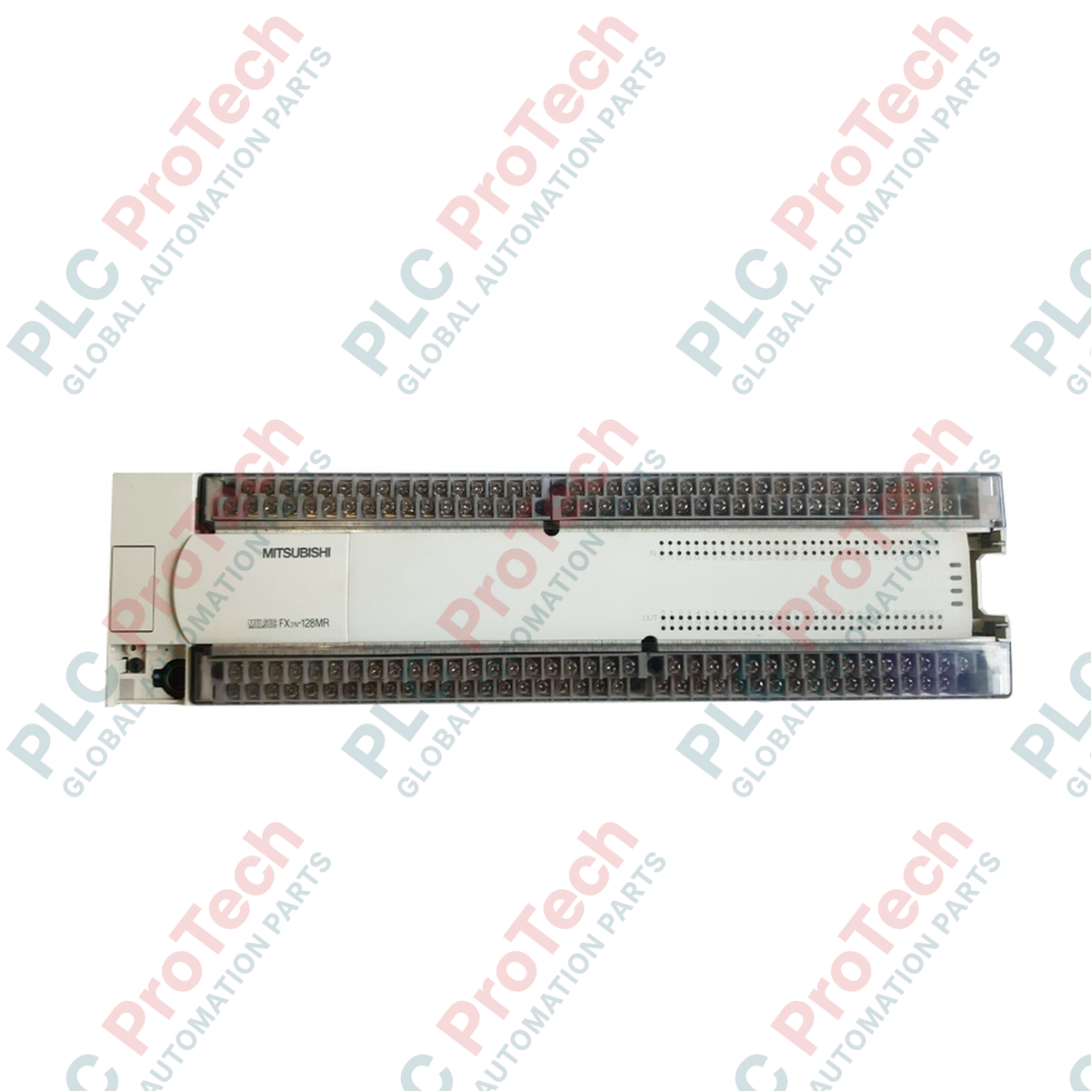
Product No.: FX2N-128MR-ES/UL
Country of origin:United States
Product Type: PLC CPU Modules
Payment: T/T, Western Union
Weight: 3000g
Dimensions: 380 x 110 x 110 mm
Shipping port: Xiamen
Warranty: 12 months
Executing high-density control sequences across manufacturing lines, the Mitsubishi Electric FX2N-128MR-ES/UL functions as the primary processing base unit within the legacy MELSEC FX2N architecture. This controller integrates processing, power supply, and extensive digital I/O within a single compact chassis, making it a reliable choice for medium-to-large industrial automation applications requiring robust relay outputs and high-speed execution.
| Parameter | Specification Value |
|---|---|
| Manufacturer | Mitsubishi Electric |
| Model Number | FX2N-128MR-ES/UL |
| Series | MELSEC FX2N |
| Input Points | 64 Points (24V DC, Sink/Source selectable) |
| Output Points | 64 Points (Relay) |
| Output Rating | 2A per point, 8A per common terminal (250V AC / 30V DC) |
| Supply Voltage | 100 to 240V AC (+10% / -15%), 50/60 Hz |
| Power Consumption | 100 VA |
| Auxiliary Power Output | 24V DC, 460 mA |
| Program Capacity | 8k steps (expandable to 16k steps with memory cassette) |
| Operating Temperature | 0 to 55 degC |
| Storage Temperature | -20 to 70 degC |
| Shipping Weight (Calculated) | 3.0 kg |
| Package Dimensions (Calculated) | 380 x 110 x 110 mm |
| Terminal / Port | Function / Circuit Assignment |
|---|---|
| L, N | AC Power Supply Input (100 to 240V AC) |
| Ground Terminal | Protective Earth (PE) ground connection |
| 24+, 24- | 24V DC Auxiliary Power Output (for sensor excitation) |
| S/S | Input Common Terminal (Sink/Source configuration selection) |
| X0 to X77 | 24V DC Digital Inputs (Octal numbering system) |
| COM0 to COM7 | Isolated Relay Output Common Terminals |
| Y0 to Y77 | Relay Output Terminals (Octal numbering system) |
The FX2N series is a legacy product line. For modern system retrofits, the FX3U-128MR/ES-A serves as the direct physical and functional successor. It utilizes the same mounting footprint and terminal block layout, though program conversion via GX Works2 or GX Developer is required to compile the legacy FX2N instruction set to the newer FX3U architecture.
Inductive loads such as solenoids, contactor coils, and magnetic valves generate significant back-EMF when switched off. To prevent premature contact welding and contact resistance degradation on the internal relays, always install external RC suppressors for AC loads or flyback diodes for DC loads. Additionally, ensure the total current drawn from the auxiliary 24V DC terminal does not exceed 460 mA, as overloading this terminal will trigger the internal overcurrent protection and shut down the input circuits.
When wiring the digital inputs, configure the S/S terminal based on your sensor type. Connect the S/S terminal to the 24V terminal for Sink input configuration (NPN sensors) or to the 0V terminal for Source input configuration (PNP sensors). Avoid running I/O signal cables in the same conduit or wire duct as high-voltage power lines to prevent electromagnetic interference from corrupting the input signals.
CRITICAL WARNING
Isolate all external power sources before attempting installation, wiring, or module replacement. Residual charges in the internal capacitors can present a shock hazard. Ensure the unit is mounted in a well-ventilated enclosure to prevent thermal buildup.
Mount the PLC base unit securely onto a 35mm DIN rail or directly to the backplate of the enclosure using the integrated mounting screw holes.
Connect the protective ground (PE) terminal to the main system ground busbar using a wire with a cross-section of at least 2.0 mm².
Wire the AC power supply lines (100-240V AC) to the L and N terminals using crimped bootlace ferrules to prevent loose strands from shorting.
Verify the S/S terminal jumper configuration matches your field sensor logic (NPN or PNP) before applying power to the unit.
Global Express Shipping
Returns & Warranty

Global Express Shipping
Returns & Warranty
Orders are processed and delivered Monday-Friday (excluding public holidays).
For full eligibility, restocking fees, and international return details, please view our official Refund & Return Policy .
| Country of origin |
United States
|