


Replacing ABB DSQC 351: Controller and Network Checks
Checks to record before replacing ABB 3HNE 00006-1 DSQC 351: controller generation, X3/X5/X20/X21 wiring, DeviceNet settings, INTERBUS mapping, and LED states.
Manufacturer: Mitsubishi Electric
Product No.: Q80BD-J71LP21-25
Country of origin:United States
Product Type: PCI Communication Boards
Payment: T/T, Western Union
Weight: 1000g
Shipping port: Xiamen
Warranty: 12 months
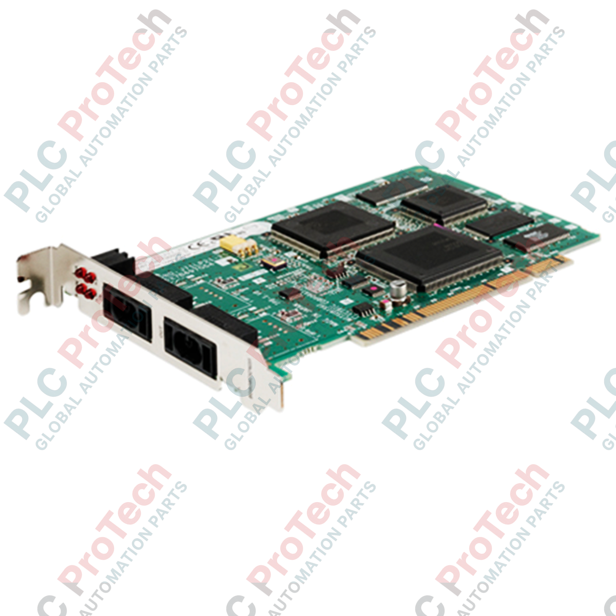
Integrating industrial PCs directly into high-speed, deterministic control networks, the Mitsubishi Electric Q80BD-J71LP21-25 serves as a dedicated optical loop network interface board designed to install into half-size PCI expansion slots. This interface card facilitates seamless real-time data exchange between a host computer and a MELSECNET/H or legacy MELSECNET/10 PLC network, offering reliable dual-loop fiber optic communication. Operating at up to 25 Mbps, it supports large-capacity cyclic transmission and transient transmission, ensuring that supervisory systems receive high-resolution field data with minimal latency.
| Parameter | Value |
|---|---|
| Manufacturer | Mitsubishi Electric |
| Model Number | Q80BD-J71LP21-25 |
| Network Type | MELSECNET/H (Optical Loop), MELSECNET/10 compatible |
| Transmission Rate | 25 Mbps / 10 Mbps (selectable) |
| Interface Slot Type | PCI Slot (half-size), occupies 1 slot |
| Maximum Connected Stations | 64 stations (1 management station, up to 63 normal stations) |
| Optical Fiber Connector Type | Duplex optical connector (F06 / F08 equivalent, JIS C 5975/5977 compliant) |
| Internal Current Consumption (5 VDC) | 0.46 A |
| Operating Ambient Temperature | 0 to 55 degC |
| Storage Ambient Temperature | -25 to 75 degC |
| Vibration Resistance | Compliant with JIS B 3502, IEC 61131-2 |
| Impact Resistance | 147 m/s2 (3 times in X, Y, Z directions) |
| Net Board Mass | 0.10 kg |
| Shipping Weight (Calculated) | 1.0 kg |
| Country of Origin | Japan |
| Connector Port | Function / Assignment |
|---|---|
| IN Port | Receives optical data from the previous network node (RX fiber) |
| OUT Port | Transmits optical data to the subsequent network node (TX fiber) |
| Gold-Plated PCI Edge | Standard 32-bit PCI bus interface for host computer communication and 5VDC power |
The Q80BD-J71LP21-25 serves as a direct upgrade over older legacy interface solutions. When executing a migration, ensure that software structures configured for the legacy MELSECNET/10 protocol are either run in compatibility mode or mapped correctly to the extended register space available in MELSECNET/H extended mode, which increases total network capacity to 35,840 bytes.
A common failure point in industrial PC integrations is PCI bus power sagging. This board draws 0.46 A strictly from the host motherboard's 5V rail. If the host backplane or power supply exhibits voltage drops under heavy processing loads, the board can experience spontaneous dropouts or diagnostic status register resets. Always verify that the host IPC power supply unit maintains a stable 5V rail within a +/- 5% tolerance.
To guarantee optimal performance at 25 Mbps, the maximum optical fiber run between stations must not exceed 200 meters when utilizing standard SI fiber. If distances up to 1 km are required, use QSI or high-bandwidth broadband H-PCF fibers. Always perform a physical loopback test during commissioning with a known good patch cable to isolate whether configuration issues originate in the local PC card setup or the external fiber network loop.
This communication board contains highly sensitive electrostatic discharge (ESD) components. Completely isolate the host computer from the mains power grid and discharge all residual capacitive charges prior to opening the chassis. Always wear a grounded wrist strap when handling the card to prevent catastrophic gate oxide damage.
Power down the host industrial computer, unplug the power cord, and remove the external chassis cover to expose the PCI slots.
Identify an empty, half-size compatible 32-bit PCI slot. Remove the corresponding blank backplate from the chassis frame.
Align the gold-plated edge connector of the card with the PCI slot, push down firmly until seated, and secure the bracket with the retention screw.
Remove the protective dust covers from the optical transceiver ports. Connect the incoming fiber optic line to the IN port and the outgoing fiber line to the OUT port, verifying the alignment pins click securely into place.
Close the PC chassis, apply power, and initiate the Mitsubishi channel utility software to configure station numbers and transmission modes.

Global Express Shipping
Returns & Warranty


Global Express Shipping
Returns & Warranty
Orders are processed and delivered Monday-Friday (excluding public holidays).
For full eligibility, restocking fees, and international return details, please view our official Refund & Return Policy .
| Country of origin |
United States
|

Checks to record before replacing ABB 3HNE 00006-1 DSQC 351: controller generation, X3/X5/X20/X21 wiring, DeviceNet settings, INTERBUS mapping, and LED states.

Compare the IC693CPU360 and IC693CPU364 by Ethernet interface, +5 VDC load, memory, rack limits, and replacement checks.

A field-first diagnostic sequence for 1756-OF4 analog output problems: channel mode, removable terminal block, scaling, and controlled electrical checks.

A direct comparison of 1746-OA8 and 1746-OA16 output count, common grouping, backplane current and temperature-derated load limits.

A field checklist for recording the 1761-NET-DNI hardware series, firmware, EDS file, DF1 settings, DeviceNet address and messaging configuration before replacement.

The EL3062 is a 0–10 V EtherCAT terminal. The EL3062-0030 is a 0–30 V variant. This checklist covers identification, scaling and commissioning.