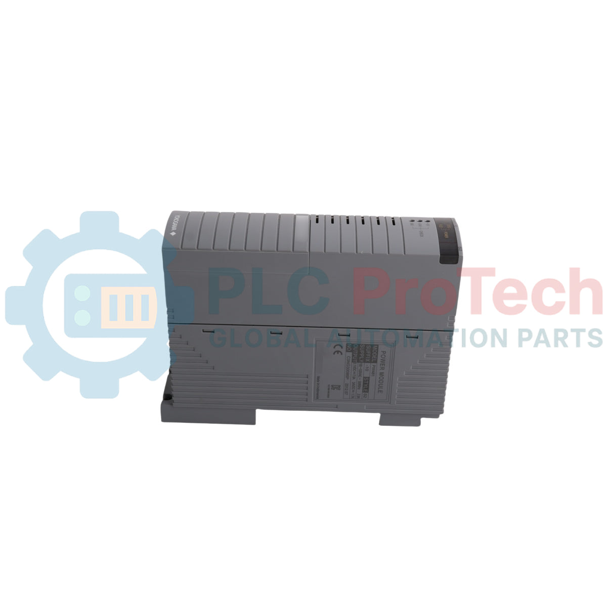
Dimensions:
149 mm x 199.5 mm x 49.7 mm (D x H x W)
Shipping port:
Xiamen
Warranty:
12 months
Description
The Yokogawa PW481-50 is a 100-120 V AC input power supply module designed for use within Yokogawa CENTUM VP control systems. The PW481-50 operates as an exclusive power supply module for Field Control Units (FCU), FIO Node Units, Optical ESB Bus Repeater Units, and base plates. Installed directly into dedicated power supply slots, the module delivers system power through an exclusive internal input/output connector interface. Dual-redundant power configurations are accomplished by installing two identical units side-by-side.
Features
Support for dual-redundant power supply configurations when using two identical modules
Designed for installation in FCUs, FIO Node Units, Optical ESB Bus Repeater Units, and Base Plates
Built with an exclusive input/output connector interface
Standard type configuration with no explosion protection
Applications
Field Control Units (AFV30D, AFV30S, A2FV50D, A2FV50S, A2FV70D, A2FV70S)
FIO Node Units (ANB10D, ANB10S, ANB11D, ANB11S)
Optical ESB Bus Repeater Units (ANT10U)
Base Plates (A2BE1D, A2BE2D)
Ordering Information
Model / Suffix Code
Description
PW481
100-120V AC Input Power Supply Module
-5
Standard type with no explosion protection
0
Basic type
Technical Specifications
Parameter
Specification
Manufacturer
Yokogawa
Model
PW481-50
Product Type
100-120 V AC Input Power Supply Module
Input Power Supply Voltage
100-120 V AC +/- 10%
Input Frequency
50/60 Hz +/- 3 Hz
Maximum Power Consumption
200 VA
Input/Output Interface
Exclusive connector
Weight
Approx. 1 kg
Dimensions
149 mm x 199.5 mm x 49.7 mm (D x H x W)
Installation Guidelines
Slot Allocation: Power supply modules must be installed in dedicated slots P1 and P2.
Single Configuration: In a single power supply configuration, install the module in slot P1.
Dual-Redundant Configuration: Dual-redundant configuration is enabled by installing two identical modules with the same model code in slots P1 and P2.
FAQ
What input voltage range is required for the power supply?
The module operates on an input voltage range of 100 to 120 V AC (+/- 10%) at a frequency of 50/60 Hz (+/- 3 Hz).
Where must the power supply be installed inside the unit chassis?
The module must be installed in slots P1 or P2. For a single module configuration, it must be placed in slot P1.
How is power redundancy implemented using this device?
Dual-redundant configuration is achieved by installing two identical modules with the same model code in slots P1 and P2.
A practical replacement guide for the GE Fanuc IC693CPU313, covering its embedded five-slot architecture, memory backup, firmware-dependent capacity and why it cannot use Series 90-30 expansion racks.
A field-focused comparison of Bently Nevada 3500/40M and 3500/42M monitor inputs, channel-pair configuration, rear I/O options, external termination hardware and firmware checks before replacement.
A field checklist for diagnosing Allen-Bradley 1746-NR4 RTD and resistance inputs, including sensor curves, lead compensation, excitation current, filter timing and channel diagnostics.
A field-focused checklist for replacing an Allen-Bradley 1785-L40B or planning a PLC-5/40 migration, covering backups, 1771 I/O mapping, DH+/RIO channels, revision risks and commissioning.
Replacing an Allen-Bradley 1747-SN scanner? Check SLC 500 logical rack and G-file mapping, link speed, cable termination, COMM/FAULT LEDs and hardware series before blaming the module or changing the...