Description
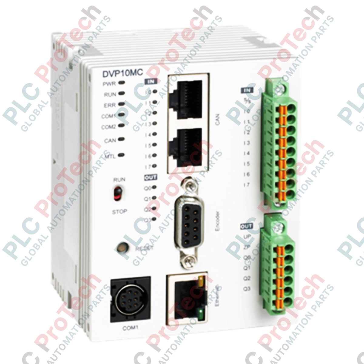
Serving as a high-performance multi-axis control node, the Delta Electronics DVP10MC11T coordinates complex motion profiles over dedicated CANopen networks. This motion controller integrates both PLC sequencing and multi-axis motion control capabilities within a single space-saving form factor, communicating directly with AC motor drives and servo systems. Designed to minimize system latency, the unit is equipped with high-speed digital inputs and transistor outputs for fast event-triggering, registration-mark sensing, and general-purpose system orchestration.
Features
-
Multi-Axis Synchronization: Controls up to 16 physical axes via a highly reliable, noise-immune CANopen motion control network.
-
Unified Control Architecture: Combines logic programming and motion control (including electronic cam, flying shear, and rotary cut) in one environment.
-
Built-In Communication Interfaces: Features onboard CANopen, Ethernet (Modbus TCP), and RS-485 (Modbus ASCII/RTU) serial ports for flexible networking.
-
High-Speed System I/O: Onboard high-speed digital inputs respond to rapid feedback pulses for precise positioning and latch functions.
-
Standard Program Execution: Supports standard PLC ladder logic and structured text alongside specialized motion control instruction blocks.
Applications
-
Packaging and Labeling Machinery: Coordinates high-speed feed axes, registration tracking, and rotary cutter mechanisms.
-
Textile Equipment: Manages electronic gear ratios and precise tension control spooling applications.
-
Material Handling Systems: Drives multi-axis gantry robots, automated sorting tables, and synchronized conveyor lines.
-
Print & Cut Systems: Synchronizes knife positioning with registration mark inputs for zero-drift continuous cutting.
Technical Specifications
| Parameter |
Specification Value |
| Manufacturer |
Delta Electronics |
| Model Number |
DVP10MC11T |
| Product Series |
DVP Series (MC Motion Family) |
| Device Type |
Network Type Motion Controller |
| Input+Output Points |
10 Points (Onboard) |
| Input Type |
DC High-Speed Input (H Type) |
| Output Type |
Transistor (Sink / NPN) |
| Controlled Axes |
Up to 16 axes via CANopen network |
| Power Supply Voltage |
24 VDC (Acceptable range: 20.4 VDC to 28.8 VDC) |
| Communication Ports |
CANopen, Ethernet, RS-485 |
| Operating Temperature |
0 to 55 degC (non-condensing) |
| Shipping Weight (Calculated) |
2.0 kg |
| Package Dimensions (Calculated) |
165 x 120 x 95 mm |
Connections and Interfaces
| Interface Node |
Functional Assignment / Terminal Definition |
| 24 VDC / 0V |
Main system control power input (Screw-type block) |
| CANopen (5-Pin) |
Motion control bus (CAN_H, CAN_L, CAN_GND, Shield, V+) |
| Ethernet (RJ-45) |
10/100 Mbps Modbus TCP & programming upload/download port |
| RS-485 (SG+, SG-) |
Modbus serial linkage for auxiliary HMI or localized peripheral integration |
Empirical Engineering Insights
Alternative Models & Compatibility
When scaling system capacity, note the performance threshold differences between the DVP10MC11T (CANopen protocol) and the DVP15MC11T (EtherCAT protocol). Program blocks built using CANopen Builder software require strict translation steps if migrating to EtherCAT-based topologies due to direct axis-mapping mechanism variations in the Delta programming software.
Application Pitfalls & Engineering Notes
Proper impedance matching on the CANopen network trunk is vital. Do not rely on internal drive terminations alone; physically install a 120-Ohm 1/4W resistor across the CAN_H and CAN_L lines at the physical ends of the communication network. Failure to do so leads to packet collision, erratic sync timings, or generic "CANopen communication timeout" drive alarm faults during high-velocity profiles.
Commissioning & Wiring Tips
Always route the 24 VDC logic power separately from the primary servo power lines. In high-noise environments, ensure that the functional earth (FE) terminal of the controller is grounded back to the central panel star ground point using a low-impedance copper strap to prevent common-mode electrical noise from interrupting the high-speed input register tracking.
Installation Guidelines
CRITICAL WARNING: De-energize all power distribution systems, upstream breakers, and drive systems before initiating mechanical mounting or I/O terminations. Verify the circuit is completely dead using a calibrated digital multimeter. Residual voltages in motor drive capacitors can back-feed the motion controller and permanently damage the CPU.
1
Snap-mount the controller onto a standard 35mm wide symmetric DIN rail. Ensure the retaining clips lock securely into place.
2
Connect the system functional earth (FE) wire directly to the chassis ground plate to reduce external high-frequency RF interference.
3
Wire the communication connectors, verifying that the CANopen shielding is continuous throughout the line segments and only grounded at one controller-end node.
4
Apply 24 VDC control power and monitor the front-panel status LEDs (POWER, RUN, ERROR) to confirm proper internal diagnostic boot procedures.