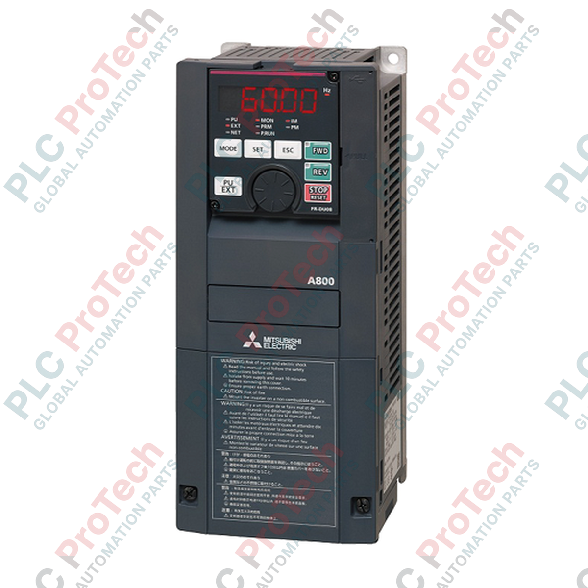
Description
Engineered to meet the demands of highly dynamic industrial motor applications, the Mitsubishi Electric FR-A820-0.75k is a premium FREQROL-A800 series variable frequency drive designed for high-precision speed and torque control. This drive accommodates multiple operating duties, including Normal Duty (ND) at 0.75 kW, Heavy Duty (HD) at 0.4 kW, and Light/Super Light Duty (LD/SLD) up to 1.5 kW, allowing electrical engineers to configure a single physical chassis for varying load profiles. By integrating advanced motor control algorithms like real sensorless vector control and PM sensorless vector control, the FR-A820-0.75k maintains stable performance and high starting torque across a broad frequency spectrum of 0.2 to 590 Hz.
Features
-
Multi-Duty Capability: Selectable SLD, LD, ND, and HD ratings to adapt to variable torque, constant torque, and high-overload profiles.
-
Advanced Control Algorithms: Selectable V/F control, advanced magnetic flux vector control, real sensorless vector control, and PM sensorless vector control.
-
Robust Overload Margins: Up to 200% for 3 seconds and 150% for 60 seconds under default Normal Duty (ND) configurations.
-
Integrated Safety Function: Features built-in safety stop capabilities conforming to international functional safety standards.
-
High-Speed Communications: Built-in RS-485 interface with native support for Modbus RTU, CC-Link, and common industrial fieldbuses.
Applications
-
Conveyor and Material Handling Systems: Providing smooth acceleration ramps and precise multi-stage speed profiles.
-
Machine Tool Spindles: Requiring stable high-speed performance and rapid, controlled braking cycles.
-
Centrifugal Pumps and Fans: Utilizing optimum excitation control to maximize energy efficiency under variable torque loads.
-
Packaging and Textile Machinery: Delivering consistent torque and tension control at low operational speeds.
Technical Specifications
| Parameter |
Specification |
| Manufacturer |
Mitsubishi Electric |
| Model Number |
FR-A820-0.75k |
| Series Name |
FREQROL-A800 |
| Power Supply Voltage |
3-Phase 200 to 240 VAC, 50 Hz / 60 Hz |
| Allowable Voltage Fluctuation |
170 to 264 VAC |
| Motor Capacity (ND / Default) |
0.75 kW |
| Motor Capacity (HD / High Duty) |
0.4 kW |
| Motor Capacity (LD / SLD) |
1.5 kW |
| Rated Output Current (ND) |
5.0 A |
| Output Frequency Range |
0.2 to 590 Hz (Vector/Sensorless limits to 400 Hz) |
| Cooling Method |
Self-cooling |
| Protective Rating |
IP20 (Closed Type) |
| Ambient Operating Temperature |
-10 to +50 degC (LD, ND, HD ratings, non-freezing) |
| Ambient Storage Temperature |
-20 to +65 degC |
| Net Weight |
2.2 kg |
| Shipping Weight (Calculated) |
3.0 kg |
Connections and Interfaces
| Terminal / Port |
Function Assignment |
| Terminals 2, 4 |
Analog input: 0 to 10 V, 0 to 5 V, or 4 to 20 mA (selectable) |
| Terminal 1 |
Auxiliary analog input: -10 to +10 V or -5 to +5 V |
| Digital Inputs (12 Points) |
Configurable control signals (Start, Forward/Reverse, Jog, Reset, Speed Selection) |
| Open Collector Outputs (5 Points) |
Configurable status signals (Run, Up-to-speed, Overload Alarm) |
| Relay Outputs (2 Points) |
Fault and high-current alarm configuration |
| RJ-45 Connector |
RS-485 Modbus RTU interface / Parameter unit connection |
Alternative Models & Compatibility
The FR-A820-0.75k directly replaces older generation FR-A720-0.75K inverters. While basic terminal block signals are layout-compatible, always review software and parameter sets using FR Configurator2 to ensure custom terminal logic mappings transition smoothly without triggering internal interlocking conflicts.
Application Pitfalls & Engineering Notes
When sizing this VFD for high starting torque loads in Heavy Duty (HD) mode, remember the maximum motor capacity is reduced to 0.4 kW. Attempting to run a 0.75 kW motor under high-vibration, high-duty cycles on the HD parameter mapping will cause rapid thermal accumulation and lead to E.THT (Inverter Overload) faults. Ensure proper clearance of at least 50 mm above and below the self-cooling frame inside sealed enclosures to avoid heat trapping.
Commissioning & Wiring Tips
For setups utilizing Real Sensorless Vector Control or PM Sensorless Vector Control, performing an offline auto-tuning sequence (Parameter 96) is highly critical. Tuning must be executed with the motor uncoupled from the gearbox or mechanical load to prevent incorrect stator resistance and inductance readings, which are the root cause of E.OC1 (Overcurrent during acceleration) errors at low speeds.
Installation Guidelines
CRITICAL WARNING: Before starting installation or maintenance, isolate all primary three-phase power supplies. Wait at least 10 minutes for the internal DC bus capacitors to discharge fully. Verify zero-voltage potential on the charge indicator LED and across terminals P/+ and N/- using a calibrated multimeter before touching internal terminals.
1
Mount the drive vertically on a flat, non-flammable surface inside a dust-free enclosure using the specified mounting screws to secure the chassis.
2
Route incoming three-phase AC mains power lines to terminal lugs R/L1, S/L2, and T/L3. Never connect mains utility voltage to the motor output terminals U, V, and W.
3
Verify that all ground connections are terminated securely using a dedicated earth terminal. Use shielded control cables for all analog and digital reference wiring to prevent electromagnetic noise interference.