Description
Facilitating seamless bidirectional communication between Ethernet and serial-based field networks, the ProSoft PLX31-MBTCP-MBS4 acts as a robust protocol converter for industrial automation systems. This module enables a Modbus TCP/IP client or server to interface directly with up to four independent Modbus Serial networks, bridging the gap between legacy serial instruments and modern Ethernet control architectures. Engineered for high-reliability environments, it provides galvanic isolation on all communication paths and features a rugged, compact enclosure designed for DIN-rail mounting. With integrated diagnostics, a flexible power supply input, and individual port configuration, this gateway ensures low-latency data transmission across diverse factory automation, water treatment, and power distribution infrastructures.
Features
-
Independent Serial Ports: Four fully isolated serial ports supporting RS-232, RS-422, or RS-485 physical layers.
-
High Electrical Isolation: 2500 Vrms port-to-port and port-to-backplane signal isolation via digital RF modulation components.
-
Robust Ethernet Interface: Single 10/100 Mbps RJ45 port featuring 1500 Vrms electrical isolation and integrated broadcast storm resiliency.
-
Flexible Power Input: Accepts a wide input range of 10 to 36 VDC, suitable for standard industrial 24 VDC control panels.
-
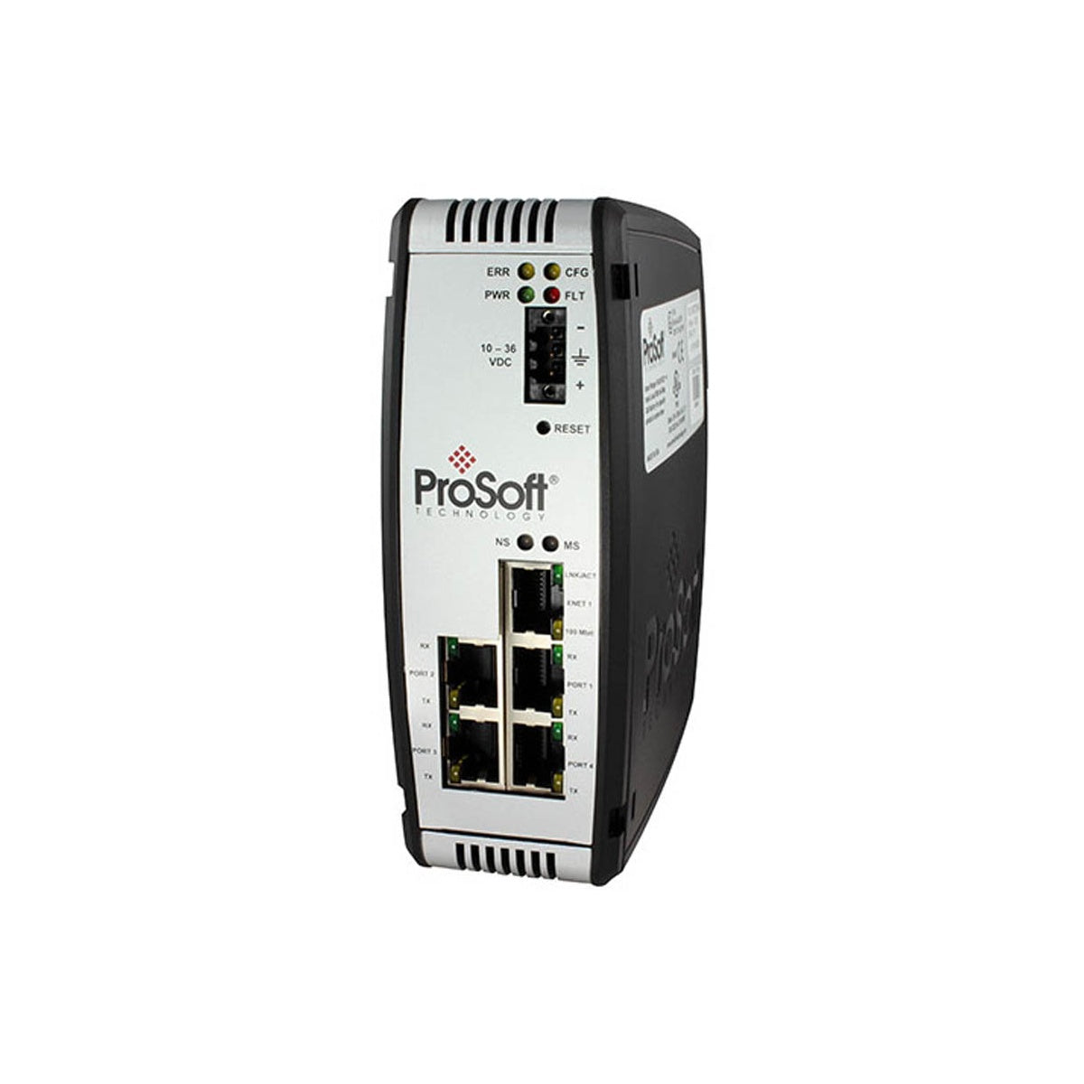
Diagnostic Indicators: Front-panel LEDs provide immediate visual confirmation of power, module status, network activity, and serial transmission (TX/RX) status.
Applications
- Integration of legacy Modbus RTU/ASCII power meters, flowmeters, and protection relays into modern Ethernet-based SCADA systems.
- Substation automation where high electrical isolation is necessary to prevent ground loops and protect centralized controller CPUs.
- Distributed water and wastewater monitoring setups requiring multi-point RS-485 serial networks linked to a centralized PLC over fiber or wireless Ethernet.
Technical Specifications
| Manufacturer |
ProSoft Technology |
| Model Reference |
PLX31-MBTCP-MBS4 |
| Power Supply Input |
24 VDC nominal (10 to 36 VDC permitted) |
| Current Consumption |
300 mA @ 24 VDC nominal (610 mA maximum @ 10 VDC) |
| Ethernet Port |
1x 10/100 Base-T RJ45 connector, half/full-duplex auto-negotiation |
| Ethernet Isolation |
1500 Vrms (50 to 60 Hz for 60 seconds) |
| Serial Interface Ports |
4x isolated serial ports (RS-232, RS-422, or RS-485 configuration) |
| Serial Port Isolation |
2500 Vrms signal isolation (UL 1577 rated, RF modulation media) |
| Operating Temperature |
-25 to 70 degC (-13 to 158 degF) |
| Storage Temperature |
-40 to 80 degC (-40 to 176 degF) |
| Relative Humidity |
5% to 95% RH (non-condensing) |
| Shock Rating |
IEC 60068-2-27: 15G operational (11ms), 30G non-operational (18ms) |
| Vibration Rating |
IEC 60068-2-6: 5G @ 10 to 150 Hz |
| Dimensions (H x W x D) |
13.67 x 5.05 x 11.13 cm |
| Shipping Weight |
2.5 kg |
Connections and Interfaces
| Port / Terminal Block |
Interface Type |
Functional Assignment |
| Ethernet Port |
RJ45 |
Modbus TCP/IP Master (Client) / Slave (Server) connection |
| Serial Port 1 to 4 |
Combicon Terminal |
Modbus RTU/ASCII Master or Slave (RS-232, RS-422, or RS-485 configuration) |
| Power Terminal |
3-Position Pluggable |
V+ (10 to 36 VDC), V- (DC Return), and Earth Ground |
Empirical Engineering Insights
Alternative Models & Compatibility
The PLX31-MBTCP-MBS4 serves as a modernized replacement for older legacy gateways. When transitioning configuration profiles from previous-generation ProSoft modules, verify database memory mappings, as the internal database register structures may require offset realignment. Use the ProSoft Configuration Builder (PCB) software for smooth parameter migration.
Application Pitfalls & Engineering Notes
A common issue during multi-port commissioning is Modbus TCP/IP transaction timeouts caused by slower serial-side responses. Ensure that your Modbus TCP master poll timeout matches the longest potential serial round-trip time. When running RS-485 configurations with high slave counts or long cable distances, external 120-ohm termination resistors must be installed at both physical ends of the trunk to prevent signal reflections.
Commissioning & Wiring Tips
The four serial interfaces feature specialized 2500 Vrms digital isolation chips. To maintain this high level of isolation performance, never share common reference or shield lines between different isolated ports or external power sources. For noisy VFD environments, utilize double-shielded twisted-pair (STP) cabling for all serial trunks and tie the cable shields directly to the cabinet ground at a single, centralized point.
Installation Guidelines
CRITICAL WARNING: De-energize all power lines before attempting to install, wire, or remove the gateway module. Touching live electrical terminations can lead to severe equipment damage, electrical shock, or physical injury. Ensure the internal system ground terminal is properly bonded to a low-impedance earth ground path before applying DC power.
1
Mount the gateway securely to an approved 35 mm DIN rail inside a protective NEMA or IP54 electrical enclosure, allowing at least 2 inches of clearance at the top and bottom for natural convective cooling.
2
Configure the internal physical serial port jumpers (underneath the front cover) to choose between RS-232, RS-422, or RS-485 modes for each of the four serial ports.
3
Connect the isolated serial network cables to the corresponding pluggable Combicon terminal blocks, ensuring correct polarity of Transmit (TX) and Receive (RX) lines.
4
Connect the Ethernet network cable to the RJ45 port and apply nominal 24 VDC power to the power supply terminal block. Monitor the LED diagnostic indicators to confirm successful module initialization.