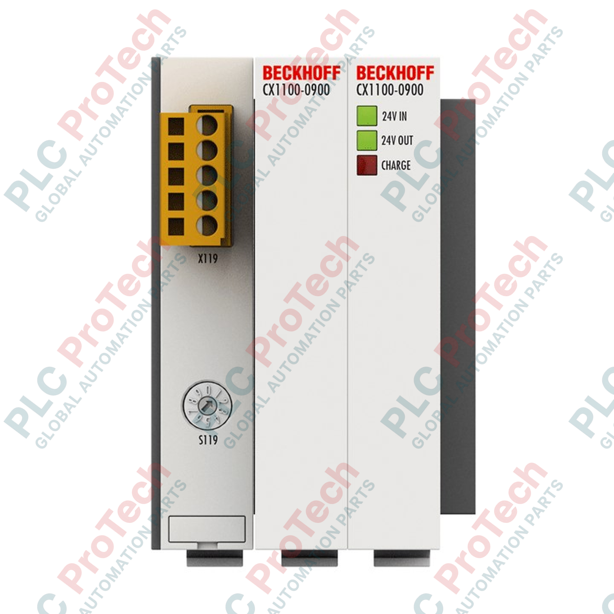
Description
Designed to provide reliable short-term backup power for Embedded PCs, the Beckhoff CX1100-0900 utilizes capacitive storage technology to safeguard critical system data during sudden power interruptions. By interfacing directly with the host controller via the internal PC/104 system bus, this module enables maintenance-free protection without the degradation risks associated with traditional battery-backed systems. The unit serves as a dependable buffer, allowing the PLC application to write active process states and retain variables directly to persistent memory before a complete system shutdown.
Features
-
Capacitive Energy Storage: Eliminates battery maintenance, wear, and thermal degradation risks, offering an extended service life.
-
Adjustable Retention Time: Configuration options allow load-dependent adjustment of backup intervals to match specific application demands.
-
Integrated PC/104 Interface: Utilizes a 16-bit ISA hardware interface for high-speed, direct communication with CX series CPU modules.
-
Comprehensive Status Monitoring: Front-panel diagnostic LEDs provide immediate visual state feedback for Input, Output, and Charge status.
Applications
- Protection of persistent variables and runtime data in Beckhoff CX1000, CX1020, and CX1030 Embedded PC systems.
- Executing controlled shutdown sequences for complex material handling and assembly machinery.
- Safeguarding recipe parameters and active batch logs in process plants during localized power failures.
Technical Specifications
| Parameter |
Specification |
| Manufacturer |
Beckhoff Automation |
| Model |
CX1100-0900 |
| Series |
CX Series (CX1000, CX1010, CX1020, CX1030) |
| Input Power Supply |
24 V DC (-15% / +20%) |
| Storage Technology |
Capacitive (Double-layer capacitors) |
| Capacity |
20 As (Ampere-seconds) |
| Retention Time |
Adjustable, load-dependent |
| Maximum Output Current |
550 mA (24 V DC) |
| Charging Current |
Max. 4 A |
| Interface to CPU |
16-bit ISA (PC/104 standard) |
| Diagnostics |
LEDs for 24 V DC Input, 24 V DC Output, and Charge |
| Maximum Power Loss |
2 W |
| Protection Rating |
IP20 |
| Operating Temperature |
0 to 55 degC |
| Storage Temperature |
-25 to 85 degC |
| Relative Humidity |
95%, non-condensing |
| Vibration/Shock Resistance |
Conforms to EN 60068-2-6 / EN 60068-2-27 |
| EMC Immunity/Emission |
Conforms to EN 61000-6-2 / EN 61000-6-4 |
| Dimensions (W x H x D) |
57 mm x 100 mm x 91 mm |
| Net Weight |
346 g |
| Shipping Weight (Calculated) |
2.0 kg |
Empirical Engineering Insights
Alternative Models & Compatibility
The CX1100-0900 belongs strictly to the first-generation CX control family (CX1000, CX1010, CX1020, CX1030). It is connected directly via the standard 16-bit PC/104 system bus on the left side of the CPU. This module is physically incompatible with newer Beckhoff Embedded PC series, such as the CX2000 or CX5100, which rely on PCIe-based bus extensions. For system migrations, verify that the existing PLC code utilizes the legacy TwinCAT system libraries rather than modern unified-UPS functions.
Application Pitfalls & Engineering Notes
Capacitive modules are designed for high-density, ultra-short-term backup applications. A total capacity of 20 As means that at the maximum rated current draw of 550 mA, the module can sustain power for approximately 36 seconds. This duration is strictly intended to execute write-to-disk or write-to-NOVRAM routines. It must not be treated as a continuous operational power supply. Thermal control is critical: operating continuously near the 55 degC limit accelerated the natural aging profile of internal double-layer capacitors, reducing actual hold-up performance over time.
Commissioning & Wiring Tips
Upon initial installation, the internal capacitors require a brief charging phase. If the charge LED is flashing or off, the module will not support full system ride-through during a power dip. Ensure your TwinCAT PLC project implements the FB_S_UPS function block. This block must be configured with the specific parameters of the CX1100-0900 to ensure that the persistent data-saving task is given execution priority immediately when the power supply status transitions from normal to battery/backup mode.
Installation Guidelines
CRITICAL WARNING:
Ensure all upstream power supplies are fully de-energized and locked out before attempting to physically couple or uncouple the CX1100-0900 module. Electrostatic and capacitive charges can remain active within the internal system bus. Failure to comply can result in damage to the PC/104 connector pins and processor instability.
1
Mount the module onto a standard 35 mm DIN rail (EN 60715) immediately to the left of the CPU module, ensuring proper spatial alignment with the bus connectors.
2
Slide the module laterally along the DIN rail until the 16-bit ISA PC/104 system bus connector plugs firmly and flush into the mating slot of the adjacent CX CPU module.
3
Engage the integrated mechanical locking mechanism to prevent axial shifting or separation of the bus contacts during operation under high vibration.
4
Apply 24 V DC system power and observe the Diagnostic LEDs. Confirm the 'Charge' LED illuminates, indicating normal initialization and capacitive cell charging.