


การเปลี่ยน Yokogawa AAI835: ตรวจสอบการเดินสายและแบริเออร์ก่อนเปลี่ยน
ก่อนเปลี่ยน Yokogawa AAI835 ให้ตรวจสอบผังช่องสัญญาณ 4 อินพุต/4 เอาต์พุต พฤติกรรมของลูปเมื่อไฟดับ ชนิดของแบร์ริเออร์ ภาระโหลดเอาต์พุต สายเคเบิล และระบบสำรองซ้ำซ้อนด้วย
Manufacturer: General Electric
Product No.: IC695PSA040
Country of origin:สหรัฐอเมริกา
Product Type: แหล่งจ่ายไฟ
Barcode: 8537101190
Payment: T/T, Western Union
Weight: 1200g
Dimensions: 3.5 ซม. x 13 ซม. x 13.5 ซม.
Shipping port: Xiamen
Warranty: 12 months
IC695PSA040 (IC695PSA040) เป็นโมดูลแหล่งจ่ายไฟประสิทธิภาพสูงขนาด 40 วัตต์ ซึ่งออกแบบมาสำหรับแพลตฟอร์ม GE PACSystems RX3i โมดูลนี้รองรับแรงดันไฟฟ้าขาเข้าแบบสากลช่วง 85 ถึง 264 VAC หรือ 100 ถึง 300 VDC และจ่ายกระจายพลังงานอย่างเสถียรผ่านแบ็กเพลนโดยตรงเพื่อขับเคลื่อนหน่วยประมวลผลและอุปกรณ์ I/O ภายในระบบ โรงงานบำบัดน้ำอัตโนมัติ โรงงานแปรรูปเคมี และสายการประกอบในภาคการผลิตอุตสาหกรรมต่างพึ่งพา IC695PSA040 (IC695PSA040) เพื่อให้การทำงานของคอนโทรลเลอร์เป็นไปอย่างคาดการณ์ได้ภายใต้สภาวะแรงดันไฟฟ้าจากโครงข่ายที่ผันผวน โมดูลแหล่งจ่ายไฟนี้แยกวงจรอิเล็กทรอนิกส์ภายในแร็กออกจากสัญญาณรบกวนทางไฟฟ้าจากภาคสนาม บันทึกข้อผิดพลาดเชิงพยากรณ์ลงในตารางของ CPU โดยตรงระหว่างเกิดความเค้นจากความร้อนหรือโหลด และยังคงความสามารถในการจ่ายไฟต่อเนื่องชั่วขณะที่รวมมาในตัว ความทนทานของสถาปัตยกรรมนี้ช่วยป้องกันการหยุดทำงานกะทันหันของ PLC ปกป้องพารามิเตอร์สำคัญขณะทำงาน และลดเวลาหยุดทำงานโดยไม่ได้วางแผนของโรงงานซึ่งมีค่าใช้จ่ายสูงได้อย่างมาก
โทโพโลยีฮาร์ดแวร์ของโมดูล IC695PSA040 มุ่งเน้นการจัดการเอาต์พุตแบบสามรางเฉพาะจุดและการป้องกันทางอิเล็กทรอนิกส์อัตโนมัติ
เอาต์พุตแรงดันไฟฟ้าแบบสามราง: จ่ายไฟ +5.1 VDC และ +3.3 VDC แยกจากกันเพื่อรองรับความต้องการของโมดูลระดับระบบ RX3i พร้อมเส้นทางเอาต์พุตรีเลย์ +24 VDC โดยเฉพาะสำหรับจ่ายไฟให้โมดูลรีเลย์เอาต์พุตภายนอก
การควบคุมกระแสเกินแบบแอ็กทีฟ: มาพร้อมวงจรจำกัดกระแสอิเล็กทรอนิกส์ในตัว ซึ่งจำกัดรางไฟ 5.1 VDC ไว้ที่ 7 แอมป์ และรางไฟ 3.3 VDC ไว้ที่ 10 แอมป์ เมื่อเกิดโอเวอร์โหลดหรือลัดวงจร แหล่งจ่ายไฟจะปิดตัวลงโดยอัตโนมัติและเริ่มพยายามรีสตาร์ทอัตโนมัติอย่างต่อเนื่องจนกว่าความขัดข้องในภาคสนามที่เป็นต้นเหตุจะได้รับการแก้ไข
การวินิจฉัยสถานะอย่างครอบคลุม: ติดตั้งไฟ LED แสดงสถานะด้านหน้าจำนวน 4 ดวง พร้อมรีเลย์วินิจฉัยภายในที่ส่งข้อมูลแบบเรียลไทม์เกี่ยวกับอุณหภูมิเกินกำหนด ภาวะโอเวอร์โหลด และสถานะความสมบูรณ์ของส่วนประกอบภายในไปยังตัวบันทึกข้อผิดพลาดของ CPU ส่วนกลางโดยตรง
| ดัชนีทางวิศวกรรม | ข้อมูลจำเพาะทางเทคนิค |
| หมายเลขรุ่น | IC695PSA040 |
| ตัวระบุแบรนด์ | GE PACSystems (General Electric) |
| ซีรีส์ระบบควบคุม | คอนโทรลเลอร์ RX3i |
| กำลังเอาต์พุตรวมตามพิกัด | กำลังเอาต์พุตรวมสูงสุด 40 วัตต์ |
| พิกัดอินพุตที่กำหนด | 120/240 VAC หรือ 125 VDC |
| ช่วงอินพุต AC | 85 ถึง 264 VAC |
| ช่วงอินพุต DC | 100 ถึง 300 VDC |
| กำลังไฟอินพุตสูงสุด | สูงสุด 70 วัตต์เมื่อมีโหลดเต็ม |
| เกณฑ์กระแสกระชาก | สูงสุด 4 แอมป์เป็นเวลา 250 มิลลิวินาที |
| ข้อมูลจำเพาะเอาต์พุตกระแส | 5.1 VDC (0 ถึง 6 แอมป์), 3.3 VDC (0 ถึง 9 แอมป์), 24 VDC (0 ถึง 1.6 แอมป์) |
| ขอบเขตแรงดันไฟฟ้า | 5.1 VDC (5.0 ถึง 5.2 VDC), 3.3 VDC (3.1 ถึง 3.5 VDC), 24 VDC (19.2 ถึง 28.8 VDC) |
| การแยกทางไฟฟ้า | 250 VAC ต่อเนื่อง (1500 VAC เป็นเวลา 1 นาทีจากอินพุตถึงแบ็กเพลน) |
| ระยะเวลาการจ่ายไฟต่อเนื่อง | อย่างน้อย 20 มิลลิวินาทีระหว่างการหยุดชะงักของแหล่งจ่ายไฟ |
| ช่วงการเดินสายภาคสนาม | สายเดี่ยวขนาด 14 AWG ถึง 22 AWG ต่อขั้วต่อ |
| ความสามารถในการต่อพ่วงแบบเดซี่เชน | สูงสุด 4 ยูนิต PSA040 |
| ขีดจำกัดอากาศขณะทำงาน | 0 ถึง 60 องศาเซลเซียส (อุณหภูมิแวดล้อมภายนอก) |
| รหัสการป้องกัน ATEX | II 3 G Ex nA IIC T3C |
| ประเทศต้นกำเนิด | สหรัฐอเมริกา |
แหล่งจ่ายไฟ IC695PSA040 สามารถกำหนดค่าแบบขนานเพื่อให้มีความซ้ำซ้อนแบบ N+1 ได้หรือไม่
ไม่ แหล่งจ่ายไฟรุ่นนี้ออกแบบมาให้ทำงานเดี่ยวภายใน Universal Backplane ของ RX3i (ซีรีส์แค็ตตาล็อก IC695) เท่านั้น ไม่สามารถใช้งานร่วมกับแหล่งจ่ายไฟอื่นเพื่อเพิ่มขีดความสามารถของระบบหรือให้ความซ้ำซ้อนของฮาร์ดแวร์ได้ การพยายามใช้งานรุ่นเก่า (รุ่น IC695PSA040C และก่อนหน้า) ร่วมกับแหล่งจ่ายไฟอีกตัวภายในช่องแบ็กเพลนเดียวกันอาจทำให้อุปกรณ์เสียหายรุนแรง
อะไรเป็นสาเหตุให้ไฟ LED แสดงสถานะ Power หลักเปลี่ยนจากสีเขียวคงที่เป็นสีเหลืองอำพัน
ไฟสีเขียวแสดงว่าโมดูลได้รับไฟและจ่ายรางไฟ DC ที่เสถียรไปยังแบ็กเพลนได้สำเร็จ ไฟสีเหลืองอำพันแสดงว่ามีการจ่ายไฟอินพุตไปยังขั้วต่อสายอินพุตของโมดูลอย่างถูกต้อง แต่สวิตช์โยกที่แผงด้านหน้าตั้งอยู่ในตำแหน่ง OFF ทำให้ไม่สามารถจ่ายไฟไปยังแร็กได้
ความขัดข้องเชิงระบบเบื้องหลังใดบ้างที่ทำให้ระบบปิดการทำงานอย่างถาวรโดยไม่แสดงไฟ LED แจ้งข้อผิดพลาดภายนอก?
มีลิงก์ฟิวส์ภายในที่ไม่สามารถซ่อมแซมได้ติดตั้งอยู่ในสายขาเข้า เพื่อเป็นระบบสำรองด้านฮาร์ดแวร์ขั้นสุดท้าย โดยปกติโมดูลจะสั่งปิดการทำงานทางอิเล็กทรอนิกส์ก่อนที่ฟิวส์นี้จะขาด แต่การลัดวงจรอย่างรุนแรงของชิ้นส่วนภายในหรือแรงดันไฟขาเข้าสูงเกินจากไฟกระชากที่รุนแรงอาจทำให้ลิงก์นี้ขาดอย่างถาวร เมื่อฟิวส์นี้ขาด ไฟแสดงสถานะการทำงานทั้งหมดจะดับลง และต้องเปลี่ยนโมดูลทั้งชุด
การลดความเสี่ยงจากไฟฟ้าช็อตและความปลอดภัยในการควบคุมเปิด/ปิด:
ระหว่างการทำงานปกติที่ใช้แหล่งจ่ายไฟ AC จะมีแรงดันไฟฟ้าอันตราย (120 VAC หรือ 240 VAC) อยู่บนโครงสร้างวงจรภายในโมดูล ต้องปิดฝาช่องเข้าถึงเทอร์มินัลด้านหน้าไว้ระหว่างการทำงานปกติ เพื่อป้องกันอันตรายจากไฟฟ้าช็อตถึงชีวิต โปรดทราบว่าสวิตช์โยก ON/OFF ด้านหน้าซึ่งอยู่หลังฝานั้นควบคุมเฉพาะขั้นเอาต์พุต DC ด้านรองเท่านั้น และไม่ตัดไฟสายขาเข้าที่มีกระแสอยู่จากเทอร์มินัลบล็อก
ข้อกำหนดการเสียบสายและขีดจำกัดแรงบิด:
ปอกฉนวนตัวนำทุกเส้นให้มีความยาวอย่างน้อย 9 มม. ถึง 11 มม. ตรวจสอบให้แน่ใจว่าเสียบสายเข้าไปในตัวเรือนเทอร์มินัลจนสุด โดยฉนวนของตัวนำแนบสนิทกับตัวหยุดฉนวนภายใน ขันแคลมป์สกรูอย่างระมัดระวัง และต้องไม่เกินแรงบิดสูงสุดที่อนุญาต 0.5 N-m (4.4 นิ้ว-ปอนด์) การเสียบไม่ถูกต้องอาจทำให้แคลมป์สกรูรัดโดนฉนวนสาย ส่งผลให้เกิดวงจรเปิดหรือจุดต่อสายร้อนผิดปกติ
ขั้นตอนการใช้จัมเปอร์ป้องกันแรงดันไฟเกินและการทดสอบ Hi-pot:
เทอร์มินัลบล็อกด้านล่างมีวงจรป้องกันไฟกระชากด้วยวาริสเตอร์โลหะออกไซด์ (MOV) ซึ่งต้องเชื่อมต่อกับกราวด์เฟรมโดยใช้จัมเปอร์ที่ผู้ใช้ติดตั้ง เพื่อให้มีการป้องกันแรงดันไฟขาเข้าสูงเกินขั้นพื้นฐาน เมื่อต้องการทดสอบไดอิเล็กทริกด้วยแรงดันสูง (Hi-pot) กับแหล่งจ่ายไฟ ต้องปิดใช้งานวงจรป้องกันแรงดันไฟเกินนี้โดยถอดจัมเปอร์ออก ติดตั้งจัมเปอร์กราวด์กลับทันทีหลังการทดสอบเสร็จสิ้น เพื่อคืนการป้องกันแรงดันกระชากชั่วขณะ


Global Express Shipping
Returns & Warranty


| Product Image | Model Number / Title | Condition | Availability | Action |
|---|---|---|---|---|
|
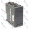
แหล่งจ่ายไฟ SLC 500 Allen-Bradley 1746-P4 | Original New | In Stock | View Details |
การจัดส่งด่วนทั่วโลก
การคืนสินค้าและการรับประกัน
คำสั่งซื้อจะถูกดำเนินการและจัดส่งในวันจันทร์ถึงวันศุกร์ (ไม่รวมวันหยุดราชการ)
สำหรับคุณสมบัติครบถ้วน ค่าธรรมเนียมการเติมสินค้าใหม่ และรายละเอียดการคืนสินค้าระหว่างประเทศ กรุณาดูที่เว็บไซต์อย่างเป็นทางการของเรา นโยบายการคืนเงินและการคืนสินค้า .
| Color pattern |
สีดำ
|
| Country of origin |
สหรัฐอเมริกา
|
| Power source |
ใช้พลังงานไฟฟ้า
|

ก่อนเปลี่ยน Yokogawa AAI835 ให้ตรวจสอบผังช่องสัญญาณ 4 อินพุต/4 เอาต์พุต พฤติกรรมของลูปเมื่อไฟดับ ชนิดของแบร์ริเออร์ ภาระโหลดเอาต์พุต สายเคเบิล และระบบสำรองซ้ำซ้อนด้วย

ABB PM891K01 บทความ 3BSE053241R1 คือชุดโปรเซสเซอร์ AC 800M แบบไม่สำรอง ใช้รายการตรวจสอบภาคสนามนี้ก่อนเปลี่ยนใหม่

การตรวจสอบเพื่อเปลี่ยนทดแทน ABB TP853 3BSE018126R1: ระบุอินเทอร์เฟซ CI853, CI855, CI857 หรือ CI861 ที่ติดตั้งอยู่ บันทึกการเดินสาย และตรวจสอบการสื่อสารหลังการติดตั้ง

การตรวจสอบทางวิศวกรรมสำหรับ Allen-Bradley 5069-L330ERMS2: ความจุของคอนโทรลเลอร์ ชุด RTB แยกต่างหาก ขีดจำกัด I/O ในพื้นที่ ขีดจำกัดจำนวนโหนดเครือข่าย และจำนวนแกนการเคลื่อนไหว

รายการที่ต้องบันทึกก่อนเปลี่ยน ABB 3HNE 00006-1 DSQC 351: รุ่นของคอนโทรลเลอร์, การเดินสาย X3/X5/X20/X21, การตั้งค่า DeviceNet, การแมป INTERBUS และสถานะ LED

เปรียบเทียบ IC693CPU360 และ IC693CPU364 ในด้านอินเทอร์เฟซอีเทอร์เน็ต โหลด +5 VDC หน่วยความจำ ข้อจำกัดของแร็ก และการตรวจสอบความเข้ากันได้สำหรับการเปลี่ยนแทน