Description
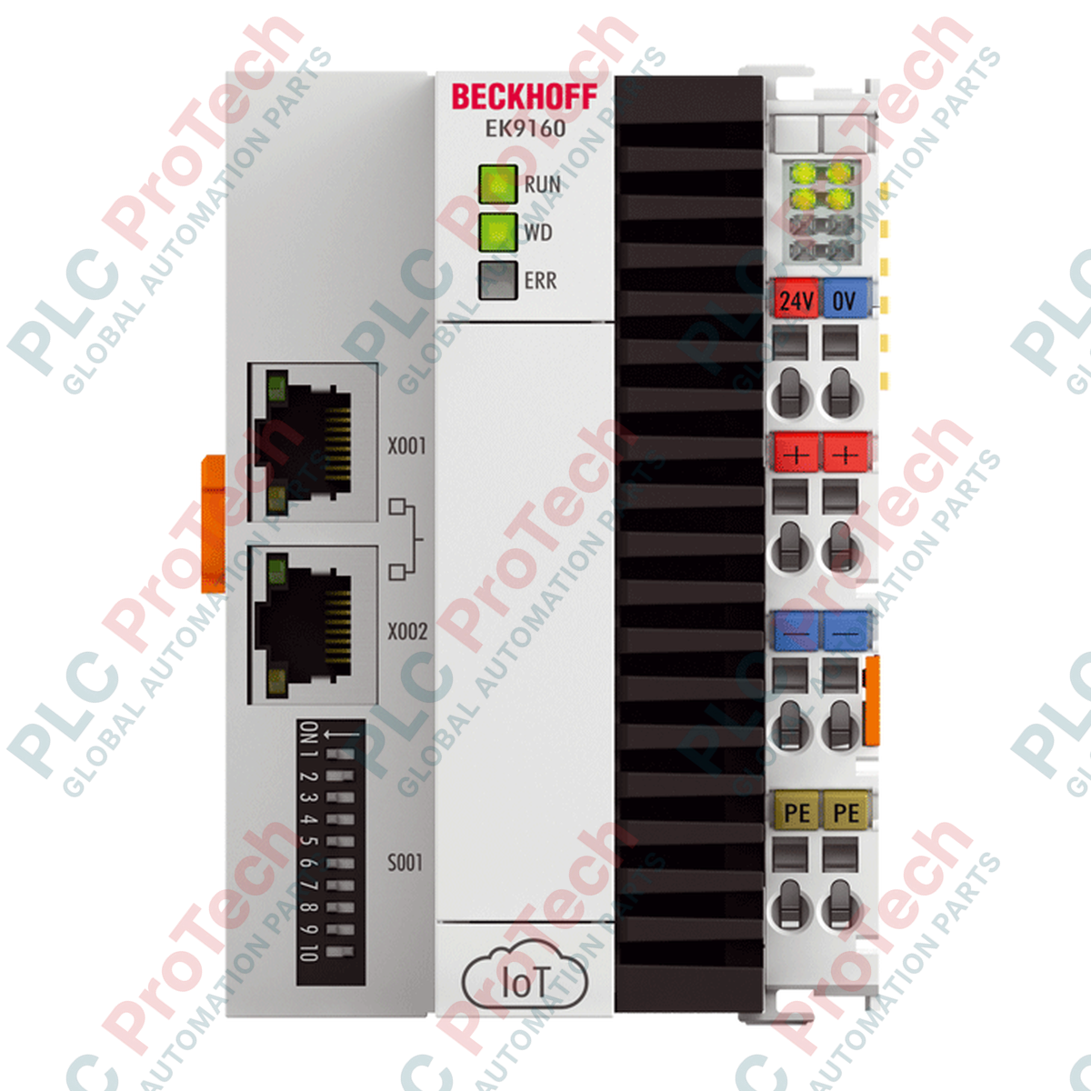
Engineered to bridge standard physical I/O systems with cloud-based architectures, the Beckhoff EK9160 transmits data from digital and analog EtherCAT Terminals directly to IoT platforms. This compact bus coupler implements native industrial protocols including MQTT and OPC UA, completely bypassing the need for an intermediate controller or control PC. Configuration is fully executed via an integrated web server, enabling fast, user-friendly setup of field data mapping to cloud endpoints. A dedicated microSD card slot (populated with a 512 MB card) provides local buffering and storage capabilities, securing critical system telemetry in the event of active network disconnections.
Key Features
- Direct integration of standard digital and analog EtherCAT Terminals to enterprise cloud infrastructures.
- Supports native MQTT and OPC UA industrial communication protocols.
- Integrated web server for rapid browser-based configuration and diagnostic visualization.
- Dual switched RJ45 ports enabling flexible industrial Ethernet line topologies.
- Onboard expandable microSD memory slot for local data logging and backup.
- Robust electrical isolation separating power contacts, supply voltages, and network ports.
Target Applications
- Industrial IoT (IIoT) architectures and smart factory analytics.
- Distributed SCADA and cloud-connected remote telemetry units (RTUs).
- Energy monitoring, logging, and predictive maintenance installations.
- Retrofits requiring direct cloud integration without disturbing existing control loops.
Technical Specifications
| Manufacturer |
Beckhoff |
| Model Number |
EK9160 |
| System Protocol |
MQTT, OPC UA |
| Data Transfer Rate |
100 Mbit/s |
| Bus Interface |
2 x RJ45 (switched) |
| Power Supply Voltage |
24 V DC (-15% / +20%) |
| Input Current |
150 mA + (total E-bus current)/4 |
| E-bus Current Supply |
2000 mA |
| Power Contacts Max |
24 V DC / 10 A maximum |
| Electrical Isolation |
500 V (power contact / supply voltage / Ethernet) |
| Flash Memory |
MicroSD slot (512 MB card included, expandable) |
| Operating Temperature |
-25 to +60 degC |
| Storage Temperature |
-40 to +85 degC |
| Relative Humidity |
95%, non-condensing |
| IP Protection Rating |
IP20 |
| Enclosure Material |
Polycarbonate (compact housing with status LEDs) |
| Mounting Format |
35 mm DIN rail (EN 60715) with lock |
| Certifications |
CE, UL |
| Physical Dimensions |
71 mm x 100 mm x 73 mm (W x H x D) |
| Shipping Weight |
5.0 kg (Approximate shipping package weight) |
Wiring Specifications
| Conductor Type |
Cross-Section Range |
AWG Compatibility |
| Solid Wire (s) |
0.08 to 2.5 mm² |
AWG 28 to 14 |
| Stranded Wire (st) |
0.08 to 2.5 mm² |
AWG 28 to 14 |
| Flexible with Ferrule (f) |
0.14 to 1.5 mm² |
AWG 26 to 16 |
| Stripping Length |
8 to 9 mm |
Empirical Engineering Insights
Alternative Models & Compatibility: The EK9160 serves a distinct, standalone role compared to standard EtherCAT Couplers like the EK1100. While standard couplers feed data back to a centralized PLC master, the EK9160 directly translates EtherCAT bus-terminal structures into IoT standard protocols (MQTT / OPC UA). It is fully compatible with standard EL and ES series digital and analog terminals, but requires careful attention to the maximum 2000 mA E-bus current budget. If total module current draw exceeds 2000 mA, supplementary power feed terminals (such as the EL9400 or EL9410) must be interspaced to avoid communication instability.
Application Pitfalls & Engineering Notes: Because data is transmitted over standard IT infrastructure directly to external or cloud-hosted brokers, network latency must be factored into application logic. Do not utilize the EK9160 for high-speed deterministic closed-loop control or safety-critical processes. Ensure the integrated web server is secure behind an industrial firewall, and avoid exposing the configuration port directly to the WAN.
Commissioning & Wiring Tips: Ensure standard industrial STP (Shielded Twisted Pair) Cat5e or Cat6 cables are utilized for connections to prevent electromagnetic interference from surrounding drive systems. Solid wires do not require tooling and can be inserted directly into the spring terminal, but stranded wires require an active spring release using a dedicated screwdriver. Do not exceed the maximum power contact current of 10 A across the DIN assembly.
Installation Guidelines
CRITICAL WARNING: De-energize all primary 24 V DC power supplies and verify complete zero-energy state prior to mounting, wiring, or swapping the bus coupler or associated terminals. Electrical discharge or live-swapping can permanently damage the sensitive internal ASIC of the E-bus communication line.
1
DIN Rail Mounting: Position the bus coupler on a standard 35 mm DIN rail (EN 60715) and lock it firmly using the integrated securing mechanism. Keep a minimum spacing of 50 mm above and below the assembly for convective cooling.
2
Terminal Assembly: Slide on the digital and analog EtherCAT Terminals side-by-side using the double slot-and-key design until they lock together. Verify E-bus connection continuity.
3
Power Connection: Wire the 24 V DC system supply using solid or stranded wires (with correct stripping length of 8 to 9 mm) to the spring-loaded power contacts. Maximum current load of 10 A across power contacts must be strictly maintained.
4
Network Connection: Connect the RJ45 industrial Ethernet cables to the integrated switch ports. Power on the system and configure network and protocol mappings through the web configuration tool.