Description
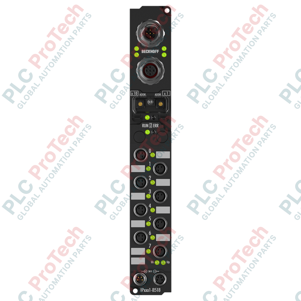
Optimizing localized I/O distribution in CANopen networks, the Beckhoff IP2321-B518 coordinates high-density automation points directly in the field. This rugged fieldbus module integrates digital inputs and outputs into a single, compact form factor designed for decentralized mounting without an electrical enclosure. Equipped with high-performance CANopen communication capabilities, the module handles signal acquisition and actuator control in demanding environments while minimizing field cabling complexities via integrated loop-through network topologies.
Key Features
-
Distributed Architecture: Compact machine-mount design eliminates the need for terminal boxes or protective control panels.
-
Hybrid I/O Configuration: Equipped with 4 digital inputs (24 V DC with a 3 ms filter time) and 4 digital outputs (24 V DC with up to 2 A output capacity per channel).
-
Fieldbus Interface: Built-in CANopen transceiver supporting high-speed industrial bus networks.
-
Integrated T-Connector: Simplifies network wiring by allowing straight-line CANopen daisy-chaining without extra external splitters.
-
M8 Connection Interface: Standardized industrial M8 screw connections ensure highly reliable, vibration-proof wiring terminations.
Applications
- Automotive assembly line conveyor networks and sorting systems.
- Decentralized packaging machinery operating in high-vibration environments.
- Machine tool automation requiring local, high-current solenoid and sensor aggregation.
- Material handling systems utilizing distributed CANopen control nodes.
Technical Specifications
| Specification Parameter |
Technical Value |
| Manufacturer |
Beckhoff |
| Model |
IP2321-B518 |
| Fieldbus Protocol |
CANopen |
| Digital Inputs |
4 Channels (24 V DC) |
| Input Filter Time |
3 ms |
| Digital Outputs |
4 Channels (24 V DC) |
| Max. Output Current |
2 A per channel |
| I/O Connection |
M8 Screw Connectors |
| Fieldbus Connection |
M12 (with integrated T-connector) |
| Operating Voltage |
24 V DC |
| Shipping Weight (Calculated) |
2.0 kg |
Empirical Engineering Insights
Alternative Models & Compatibility
The IP2321-B518 is tailored for CANopen-based control networks. When transitioning legacy plants from CANopen to EtherCAT architectures, this module cannot be directly converted to EtherCAT. Systems integration engineers should look toward the Beckhoff EP2338-0002 EtherCAT Box as a high-density alternative, or utilize a local EtherCAT-to-CANopen coupler gateway to retain existing IP2321-B518 field runs without replacing field-level physical wiring.
Application Pitfalls & Engineering Notes
While the module supports up to 2 A output current per channel, commissioning engineers must calculate the total aggregate load current for all active outputs. Exceeding the cumulative terminal current capabilities on the M8 auxiliary power feed can lead to localized thermal stress or unexpected low-voltage faults on the control side of the circuit, causing the module to shut down its outputs to protect internal solid-state components.
Commissioning & Wiring Tips
When deploying CANopen networks with the integrated T-connector, ensure that the network's physical ends are terminated with proper 120-Ohm resistors. To maintain the IP67 ingress protection rating, all unused M8 and M12 sockets must be sealed with Beckhoff protective caps and torqued to approximately 0.4 Nm. Over-tightening can crack the structural plastic threads, destroying the module's moisture-tight seal.
Installation Guidelines
CRITICAL SAFETY WARNING
Ensure all primary electrical systems, control voltages, and actuator auxiliary supplies are fully de-energized before mounting, wiring, or configuring the fieldbus module. Failure to isolate power lines can result in severe equipment damage, electrical shock, or unexpected mechanical movements of connected field machinery.
1
Securely mount the module directly to the machine frame using standard mounting holes, ensuring the mating surface is flat to prevent mechanical twisting when tightened.
2
Configure the CANopen node address using the protected rotary switches. Ensure node IDs do not overlap with other active fieldbus devices.
3
Connect the M8 digital inputs and outputs, paying careful attention to the keyway orientation of the sensor and actuator cables.
4
Attach the incoming and outgoing CANopen network links via the integrated T-connector. Verify that the bus line is properly terminated at the network physical boundaries.
5
Apply the 24 V DC system power supply and load supply lines, then run standard network diagnostic scans in your controller to verify node communication stability.