Description
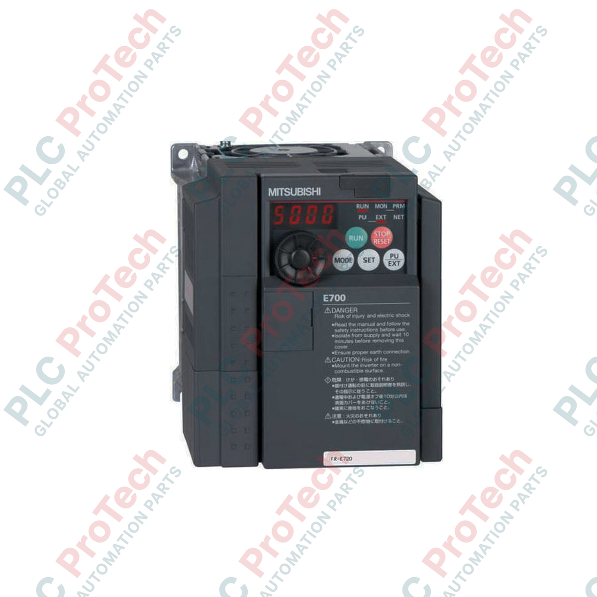
Engineered to deliver high-performance motor speed control in heavy industrial configurations, the Mitsubishi Electric FR-E720-5.5K is a three-phase 200V class variable frequency drive from the esteemed FR-E700 Series. Built to handle standard and heavy-duty torque demands, this 5.5 kW (7.5 HP) inverter integrates advanced magnetic flux vector control to supply reliable low-speed torque and dynamic responsiveness. It serves as a dependable control element for machinery requiring rapid acceleration, deceleration, and high-precision velocity regulation.
Features
-
High-Performance Vector Control: Advanced magnetic flux vector control algorithm delivers 150% torque at speeds as low as 1 Hz.
-
Compact Enclosure Footprint: Space-saving chassis design allows side-by-side installation to minimize control panel volume.
-
Removable Terminal Block: Simplifies wiring maintenance and reduces system downtime during hardware swap-outs.
-
Safety-Stop Functionality: Integrated dual-channel emergency stop input complies with international safety standards (EN ISO 13849-1 Category 3 / PLd).
-
USB Configuration Interface: Dedicated diagnostic port permits rapid parameter upload, download, and real-time monitoring via FR Configurator software.
Applications
-
Material Handling: High-torque conveyor systems, sorting machines, and lifters.
-
Process Machining: Variable speed control for mixers, agitators, and industrial centrifuges.
-
Fluid Management: Constant torque control of positive displacement pumps and centrifugal pumping stations.
-
HVAC Systems: Air handling unit fans, industrial blowers, and exhaust ventilation assemblies.
Technical Specifications
| Parameter |
Specification Value |
| Manufacturer |
Mitsubishi Electric |
| Model / Article Number |
FR-E720-5.5K |
| Product Series |
FR-E700 Series |
| Voltage Class |
Three-phase 200V class (200 to 240V AC, 50/60Hz) |
| Inverter Capacity |
5.5 kW (7.5 HP) |
| Recommended MCCB (No Reactor) |
50 A |
| Recommended MCCB (With Reactor) |
40 A |
| Magnetic Contactor (MC) |
S-N25 |
| Control Logic Options |
Sink (NPN) or Source (PNP) selectable |
| Cooling Method |
Forced air cooling (with cooling fan) |
| Net Weight |
4.3 kg |
| Shipping Weight (Calculated) |
7.0 kg |
Connections and Interfaces
| Terminal Symbol |
Function Description |
| R/L1, S/L2, T/L3 |
Main power input terminals (Three-phase 200-240V AC) |
| U, V, W |
Inverter output terminals connected directly to the AC induction motor |
| STF / STR |
Forward Run / Reverse Run terminal contact command |
| SD |
Common terminal for control input contacts (Sink common) |
| PC |
Common terminal for transistor outputs and external power source (Source common) |
| 10, 2, 5 |
Analog voltage input interface (0 to 10V DC speed reference) |
| 4, 5 |
Analog current input interface (4 to 20mA speed reference) |
| A, B, C |
Form C relay output contact (Fault/Alarm indicator) |
Empirical Engineering Insights
Alternative Models & Compatibility
The FR-E720-5.5K serves as a direct upgrade to legacy FR-E520-5.5K models. Keep in mind that control terminal dimensions and layout differ; the FR-E700 series utilizes a removable control connector card which is not physically compatible with FR-E500 backplanes. Parameter maps are highly consistent, though parameter settings for vector control (Pr. 80 and Pr. 81) must be manually reconfigured to match the motor's slip frequency and excitation current.
Application Pitfalls & Engineering Notes
During constant torque operation at frequencies below 10 Hz, standard non-ventilated AC motors can overheat rapidly. Under these conditions, specify a force-cooled motor or derate the load. Ensure the continuous ambient temperature in enclosed panels does not exceed 50 degC. If installing multiple drives side-by-side inside a single cabinet, the top shielding plates must be removed to guarantee proper airflow convection.
Commissioning & Wiring Tips
To transition the digital inputs from standard Sink logic (NPN) to Source logic (PNP), isolate the main power and toggle the physical logic selector switch located directly beneath the control circuit terminal block. When commissioning through terminal 4 (4-20mA current input), set parameter AU (Pr. 184) to activate Terminal 4 input. Run twisted, shielded-pair (STP) wiring for all analog reference cables and ground the shield only at the drive end (Terminal 5) to isolate signal lines from high-frequency common-mode noise.
Installation Guidelines
CRITICAL SAFETY WARNING
Before installing or servicing this drive, fully isolate the mains input power. Wait at least 10 minutes for the internal DC bus capacitors to discharge. Verify the DC bus voltage across terminals P/+ and N/- is below 30V DC using a certified digital multimeter. Failure to follow discharge protocols can result in severe electrical shock, personal injury, or equipment destruction.
1
Mechanical Mounting: Mount the drive vertically to a flat, non-flammable back panel using M5 screws. Maintain at least 50mm clearance on both sides and 100mm clearance above and below the unit for heat dissipation.
2
Main Power Wiring: Connect three-phase 200V supply conductors to terminals R/L1, S/L2, and T/L3 via the recommended 50A MCCB. Connect the motor leads to U, V, and W. Ensure the protective earth (PE) terminal is securely grounded using a low-impedance copper conductor.
3
Control Circuit Integration: Wire standard start/stop signals to the STF/STR inputs. If external analog controls are required, connect the input references to terminal 2 or 4. Check the position of the Sink/Source jumper switch to match external PLC I/O configurations.
4
Initial Power-Up and Calibration: Energize the unit and set motor nameplate data, including rated voltage, current, and frequency. Execute an off-line auto-tuning sequence (Pr. 96) to optimize the internal motor flux model for efficient and stable dynamic performance.