Description
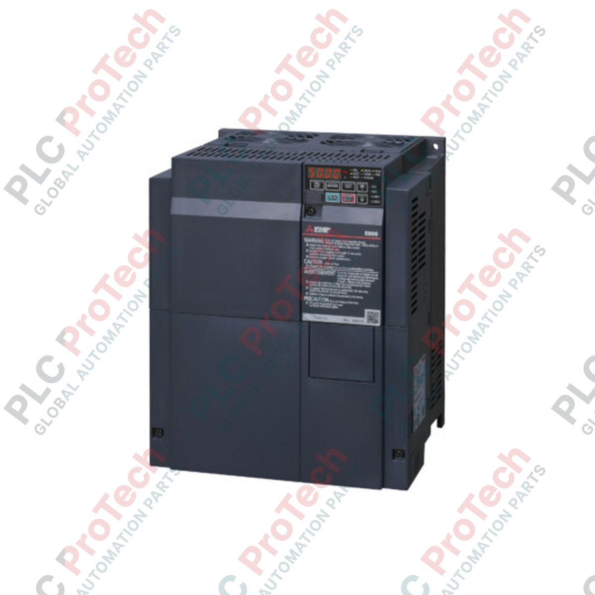
Engineered to deliver highly reliable speed and torque regulation for three-phase induction and permanent magnet motors, the Mitsubishi Electric FR-E840-0300-4-60 is a high-performance 400V class variable frequency drive from the robust FR-E800 family. This specific configuration features a rated normal duty (ND) current of 30.0 A, utilizing source logic for safety and input control configurations. To ensure durability in harsh industrial manufacturing environments, this unit is supplied with conformal board coating (-60 designation), safeguarding critical control circuits from airborne contaminants, moisture, and conductive dust.
Key Features
-
Conformal PCB Coating: Manufactured with protective circuit board coating to comply with demanding atmospheric conditions.
-
Optimized Input Configuration: Configured for 400 V class three-phase input systems with an initial base frequency setting of 50 Hz.
-
Source Logic Interface: Standard safety stop and digital input configurations utilize source logic wiring protocols.
-
Analog Monitoring: Includes terminal AM voltage analog output for precise real-time operational feedback.
-
Advanced Thermal Design: Forced-air cooling system engineered for optimal heat dissipation within compact electrical enclosures.
Applications
- Automated material handling and conveyor line control systems.
- Industrial pump networks and local fluid distribution systems.
- HVAC ventilation, heavy-duty industrial fan systems, and blowers.
- Packaging, wrapping, and secondary assembly machinery.
Technical Specifications
| Specification Parameter |
Value / Rating |
| Manufacturer |
Mitsubishi Electric |
| Model Number |
FR-E840-0300-4-60 |
| Product Series |
FR-E800 Series |
| Voltage Class |
400 V Class (Three-Phase Input) |
| Rated ND Current |
30.0 A |
| Initial Base Frequency |
50 Hz |
| Control Logic Type |
Source Logic |
| Circuit Board Coating |
With Conformal Coating |
| Plated Conductor |
Without Plating |
| Safety Circuitry |
Source Logic (Fixed), STO Capable |
| Monitoring Terminal |
Voltage Output (Terminal AM) |
| Net Weight |
4.9 kg |
| Shipping Weight (Calculated) |
7.0 kg |
Connections and Interfaces
| Terminal Block |
Terminal Label |
Function / Circuit Assignment |
| Main Power Circuits |
R/L1, S/L2, T/L3 |
Three-phase AC power input connections |
| U, V, W |
Three-phase AC output connections to motor |
| Control & Monitoring |
AM |
Analog voltage monitoring (0 to 10 VDC) |
| PC |
External 24 VDC power supply common (Source logic reference) |
| S1, S2, SIC |
Safety stop signal inputs (Source logic configuration) |
Empirical Engineering Insights
Alternative Models & Compatibility: The FR-E840-0300-4-60 acts as a modern replacement for legacy FR-E740 series configurations. When upgrading, engineers must account for minor physical housing adjustments and use FR Configurator2 software to systematically convert the parameter map, particularly verifying that safety circuit wiring is transitioned to match the fixed source safety logic of the E800 series.
Application Pitfalls & Engineering Notes: Although the conformal coating on this model (indicated by the -60 suffix) provides increased protection against chemical gases and dust ingress, the drive unit must still be mounted vertically within a clean air environment or sealed NEMA 12/IP54 enclosure if high-density metallic dust is present. Avoid installing the drive horizontally, as this disrupts the convective heat flow and reduces the cooling capacity of the onboard fans.
Commissioning & Wiring Tips: Ensure control signaling cables are run through dedicated, grounded steel conduits separate from the main motor output lines. Always wire the analog AM monitoring terminal using shielded twisted-pair (STP) cabling to eliminate high-frequency electromagnetic interference (EMI) from the drive's internal IGBT switching actions.
Installation Guidelines
CRITICAL WARNING: Hazardous voltages persist on power terminals even after line-side power is removed. De-energize all primary input sources and wait a minimum of 10 minutes for internal DC bus capacitors to discharge safely below 50 VDC. Always verify zero voltage state with an engineered digital multimeter before touching power circuitry.
1
Mechanical Mounting: Fasten the VFD vertically to a flat, non-combustible rear panel using appropriate M5 mounting screws. Ensure a minimum of 50 mm space above and below the cooling duct path.
2
Earth Grounding: Establish a low-impedance ground connection directly to the main system PE bus. Do not daisy-chain ground terminals across adjacent drives.
3
Power Terminals: Wire the main AC lines to R/L1, S/L2, and T/L3, and connect the corresponding motor phases to U, V, and W. Ensure all wire terminations are torqued to manufacturer specifications.
4
Control Logic Inspection: Verify the external control loops match the source logic configuration, connecting terminal PC as the digital common reference.