Vue d'ensemble opérationnelle et intégration du système d'entraînement
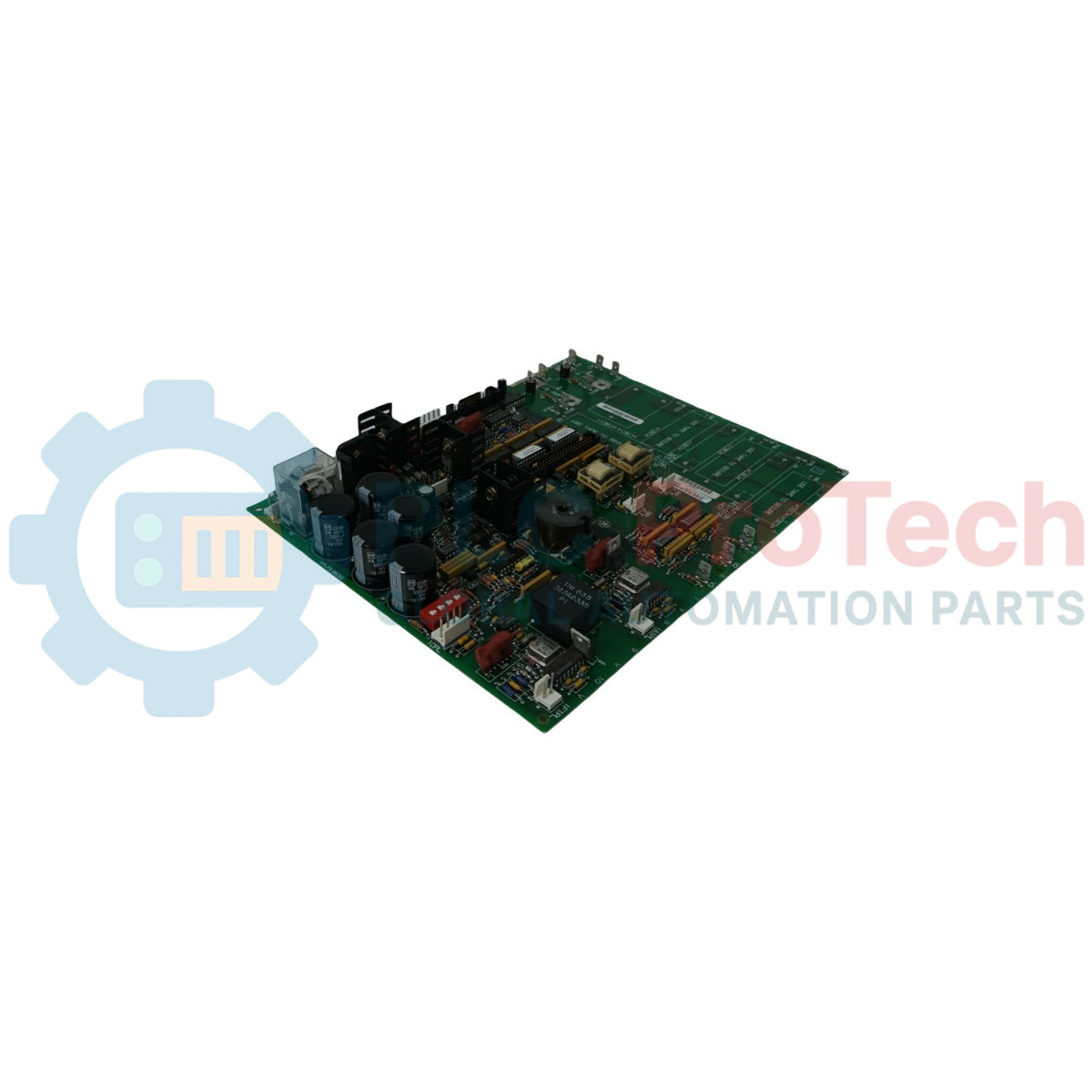
La 531X306LCCBFM1 (531X306LCCBFM1) est une carte de communication réseau local (LAN) à haute fiabilité développée par General Electric pour ses plateformes de contrôle d'entraînement industrielles héritées, incluant les systèmes Mark V et Drive Control Systems (DCS). Cette carte coprocesseur de communication agit comme interface réseau dédiée entre les processeurs principaux de contrôle d'entraînement et les réseaux d'automatisation périphériques. Fonctionnant dans des secteurs industriels exigeants — tels que les laminoirs à acier, les lignes de fabrication de papier, les systèmes de propulsion marine et les centrales électriques — la 531X306LCCBFM1 (531X306LCCBFM1) exécute des transmissions de données à haute vitesse et déterministes. En déchargeant le microprocesseur principal de contrôle d'entraînement des lourdes tâches de communication série et de traitement des protocoles réseau, elle garantit une réactivité en temps réel pour les paramètres critiques des boucles de vitesse et de couple. Cette architecture de traitement efficace minimise la latence des données, élimine les délais de communication et réduit considérablement les arrêts de fonctionnement imprévus.
Interface de communication et cœur matériel
L'architecture technique de la carte réseau 531X306LCCBFM1 se concentre sur une transmission de signal robuste et des configurations flexibles des liaisons de communication.
-
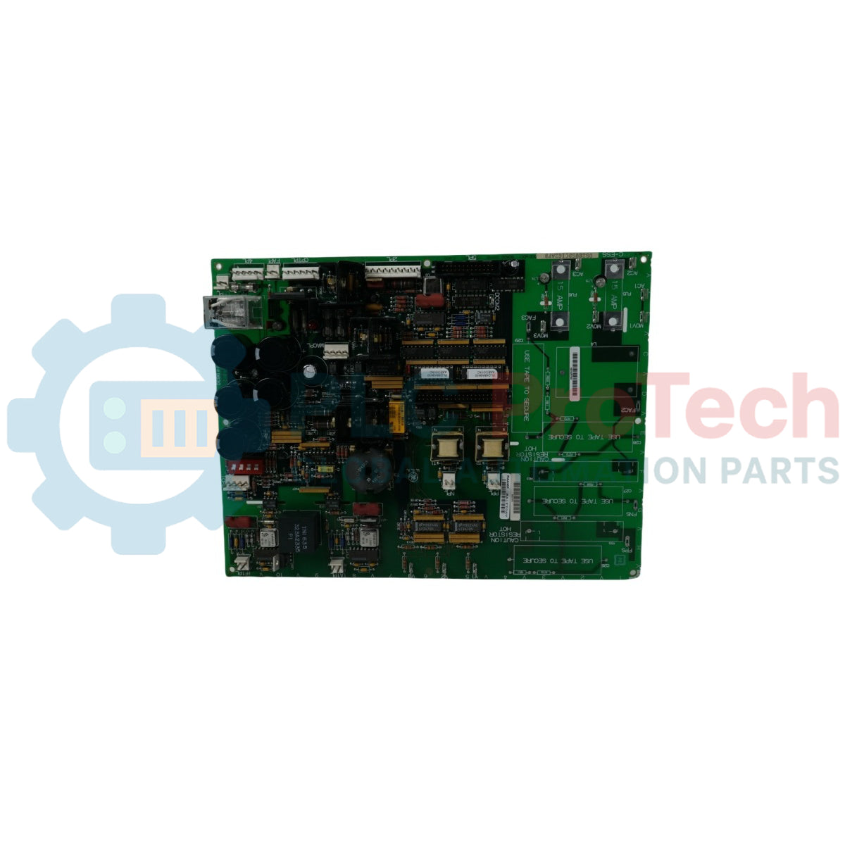
Routage coaxial et fibre optique : Prend en charge des liaisons LAN à haute vitesse, offrant des terminaux natifs pour câblage coaxial standard ou des émetteurs-récepteurs fibre optique afin de maintenir une clarté optimale du signal sur de longues distances.
-
Puissance de traitement embarquée : Équipée d’un sous-système microprocesseur indépendant qui gère de manière autonome le trafic de la couche réseau, la vérification des erreurs et la gestion des paquets en anneau token.
-
Protection par isolation galvanique : Dispose de transformateurs d’isolation dédiés embarqués qui protègent les circuits logiques sensibles contre les interférences électromagnétiques (EMI) et les différences de potentiel de boucle de terre fréquentes dans les armoires d’entraînement lourdes.
Indices de performance physique et électrique
| Indice de paramètre |
Spécification technique |
| Numéro de modèle |
531X306LCCBFM1 |
| Marque |
General Electric (GE) |
| Classification du composant |
Carte de communication LAN / Carte coprocesseur |
| Compatibilité système d'entraînement |
Sous-systèmes GE Drive Control / Mark V |
| Protocoles réseau |
DLAN (Drive Local Area Network) / Protocoles spécialisés GE |
| Tensions d'alimentation logique |
5 VCC / 15 VCC (provenant du backplane principal de l'entraînement) |
| Type d'isolation |
Accoupleurs par transformateur et lignes de données optocouplées |
| Diagnostic embarqué |
LEDs d’état pour transmission (TX) et réception (RX) |
| Température de fonctionnement |
0 à 60 °C |
| Plage de température de stockage |
-40 à 85 °C |
| Contraintes d'humidité |
5 à 95 % HR (sans condensation) |
| Dimensions physiques |
Format standard de carte GE Drive Control |
FAQ techniques
Comment configure-t-on l'adresse de nœud spécifique sur la carte 531X306LCCBFM1 ?
L’adressage des nœuds réseau se gère directement sur la carte à l’aide d’interrupteurs DIP manuels ou de cavaliers situés près du connecteur de bord. Avant d’insérer la carte de remplacement, lisez le motif des interrupteurs sur la carte défaillante et reproduisez précisément les positions sur la nouvelle carte d’origine. Une configuration incorrecte des nœuds crée des conflits de collision réseau et provoque une perte de communication du contrôleur d’entraînement.
Que signifie une LED de diagnostic inactive ou clignotante sur le panneau avant ?
La carte est équipée de LEDs de diagnostic indiquant les boucles actives de transmission (TX) et de réception (RX). Si les LEDs ne clignotent pas lors de l’initialisation du système, cela signifie une perte totale de communication en anneau token. Vérifiez l’intégrité de la liaison coaxiale ou fibre, contrôlez les résistances de terminaison aux extrémités du segment et assurez-vous que le rail d’alimentation du backplane fournit une tension stable de 5 VCC à la logique de la carte.
Est-il possible de réparer ou remplacer des composants sur cette carte directement sur le terrain ?
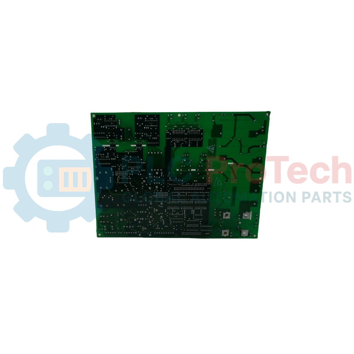
Le remplacement de composants sur le terrain n’est pas recommandé en raison de la construction multilayer du circuit imprimé et des dispositifs montés en surface (CMS) délicats. En cas de défaillance matérielle, la stratégie la plus efficace pour éviter un arrêt prolongé est de substituer la carte défectueuse par une unité de remplacement certifiée et d’envoyer la carte endommagée à un dépôt agréé pour une réparation diagnostique sensible à l’électricité statique.
Ingénierie terrain et protocole d'installation
-
Protection contre les décharges électrostatiques (ESD) :
La carte 531X306LCCBFM1 utilise des composants CMOS haute densité très sensibles aux décharges statiques. Les techniciens terrain doivent porter un bracelet antistatique correctement mis à la terre avant d’extraire la carte de son sac de protection statique ou de l’insérer dans le châssis d’entraînement. Manipulez la carte uniquement par ses bords en fibre de verre ou ses leviers en plastique.
-
Blindage et contrôle du câblage :
Les lignes de communication LAN doivent être entièrement séparées des lignes moteur AC haute tension et du câblage d’alimentation triphasé de l’entraînement. Si un média coaxial cuivre est utilisé, le blindage extérieur doit être mis à la terre en des points uniques spécifiques conformément au manuel système GE pour éliminer les boucles de terre. Assurez-vous que tous les connecteurs BNC ou à bornes sont bien serrés pour éviter les pertes de paquets dues aux vibrations.
-
Sécurité d’alimentation du backplane – mise hors tension :
Ne jamais brancher ou débrancher la carte de communication lorsque le rack de contrôle d’entraînement GE est sous tension. L’insertion à chaud génère des arcs électriques intenses sur les connecteurs multipoints, risquant d’endommager gravement les bus logiques internes de la carte et de corrompre les registres de configuration en cours dans les modules d’entraînement adjacents. Coupez toujours d’abord le disjoncteur principal de l’armoire.