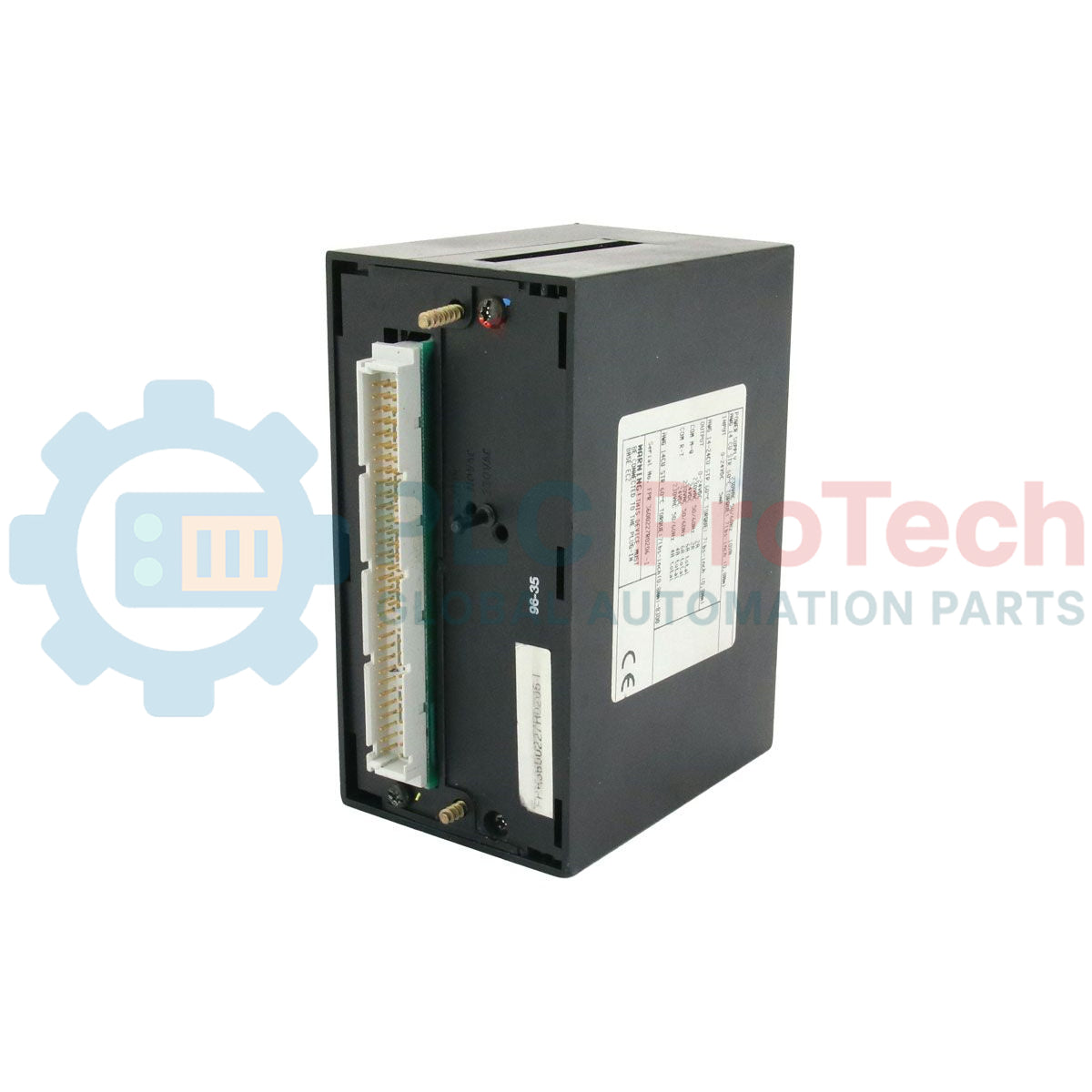
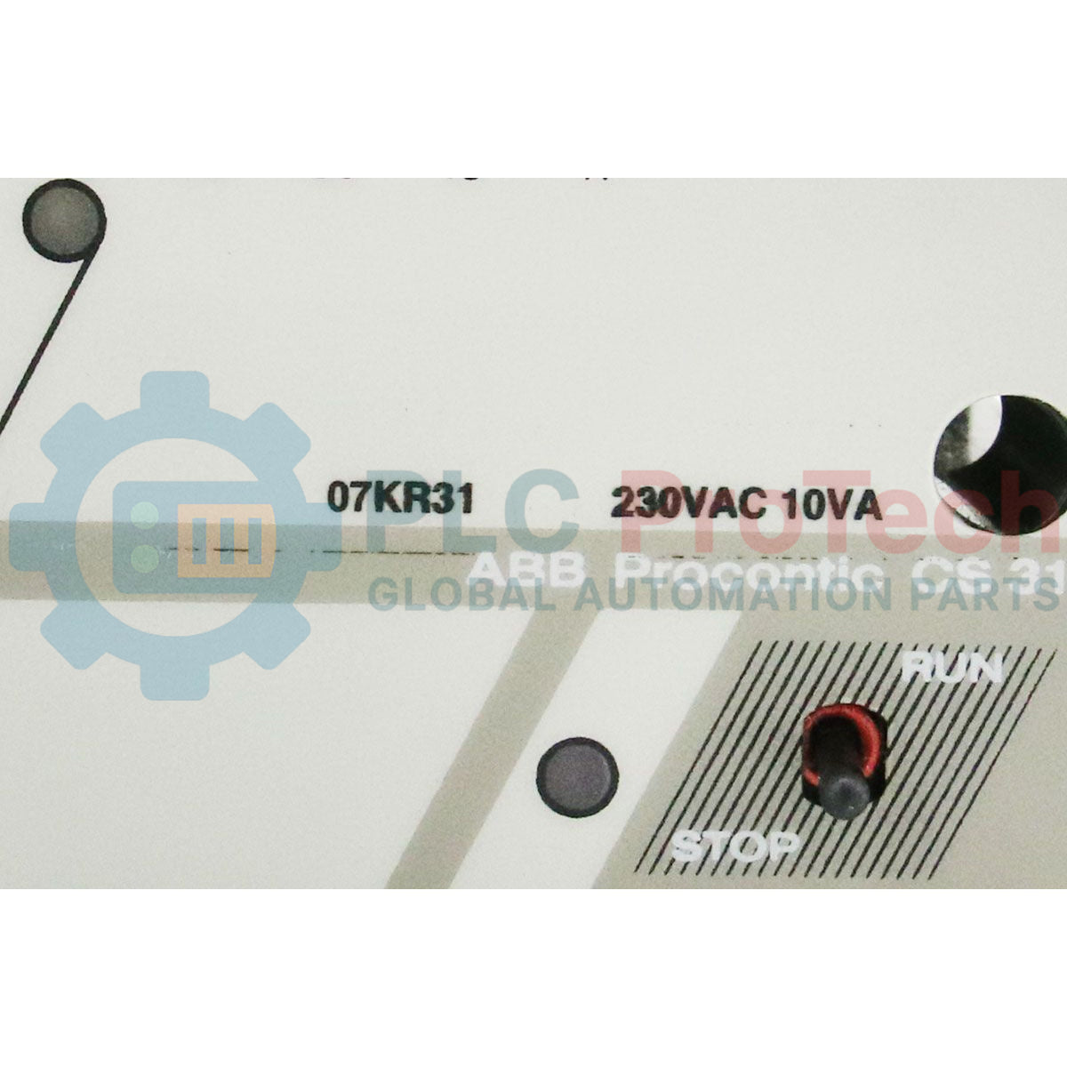
Le 07 KR 31 (07KR31), également identifié sous le numéro de pièce FPR3600227R1202, est une unité centrale de traitement (CPU) haute performance spécialement développée pour la série ABB Procontic. Ce contrôleur est une pierre angulaire des systèmes d'automatisation et de contrôle industriels hérités dans des secteurs tels que la métallurgie, la fabrication de machines spécialisées et le traitement chimique. À une époque où la disponibilité des systèmes est cruciale, le 07 KR 31 offre une plateforme stable et robuste pour gérer une logique numérique et analogique complexe. Son alimentation intégrée en 24 VDC et son support de l'architecture de bus distant CS31 permettent une stratégie de contrôle distribuée, permettant aux ingénieurs de maintenir une infrastructure héritée avec une grande fiabilité tout en évitant les coûts prohibitifs d'une refonte totale du système.
Cadre architectural et cartographie
Le 07 KR 31 fonctionne comme un contrôleur maître capable de gérer un grand volume de données E/S via sa mémoire interne et ses interfaces de bus externes.
-
E/S intégrées : L’unité de base comprend 12 entrées numériques locales (E 62,00 à E 62,11) et 8 sorties relais numériques (A 62,00 à A 62,07), offrant une capacité de contrôle immédiate sans modules périphériques.
-
Extension bus CS31 : Il supporte une vaste gamme d’E/S distantes, pouvant accueillir jusqu’à 61 modules distants. Cela permet de traiter en temps réel des milliers de drapeaux binaires (M-flags) et des centaines d’opérandes basés sur des mots (MW).
-
Traitement haute vitesse : Des adresses matérielles dédiées gèrent le comptage haute vitesse et la détection de passage par zéro (E 63,13 et E 63,14), essentiels pour des tâches de positionnement précis ou basées sur la fréquence.
-
Logique de diagnostic : La CPU réserve des zones mémoire spécifiques (plage M 255,00) pour les diagnostics système, garantissant que les défauts matériels ou les erreurs de bus sont immédiatement capturés et signalés à l’IHM ou au système de supervision.
Performances et spécifications matérielles
| Paramètre |
Spécification |
| Modèle |
07 KR 31 (07KR31) |
| Numéro de pièce |
FPR3600227R1202 |
| Marque |
ABB |
| Série |
Procontic |
| Tension d’alimentation |
24 VDC |
| Entrées numériques locales |
12 entrées (24 VDC) |
| Sorties numériques locales |
8 sorties relais |
| Fonctions de comptage |
Compteur haute vitesse & compteur de passage par zéro |
| Poids net du produit |
0,40 kg |
| Dimensions physiques |
10,20 x 7,60 x 12,70 cm |
| Température de fonctionnement |
0 à 55 degrés Celsius |
| Statut du produit |
Obsolète (Support hérité disponible) |
FAQ Support Expert
Le 07 KR 31 est-il directement compatible avec les modules 07 KT 31 ?
Oui, le 07 KR 31 est conçu pour s’intégrer parfaitement avec les modules de la série 07 KT 31 et divers modules fonctionnels, permettant une extension du traitement analogique et des tâches de contrôle spécialisées dans le même rack ou bus.
Comment la CPU gère-t-elle les fluctuations de puissance dans un environnement 24 VDC ?
L’alimentation interne 24 VDC est de qualité industrielle, conçue pour supporter les tolérances de tension standard en milieu industriel. Cependant, pour les environnements à forte perturbation électrique ou instables, une alimentation régulée externe et un parasurtenseur sont recommandés.
Quelle est la méthode principale pour dépanner les erreurs de communication sur le bus ?
Les utilisateurs doivent surveiller les drapeaux de diagnostic allant de M 255,00 à M 255,15. Ces drapeaux fournissent des codes d’erreur spécifiques liés à l’intégrité du bus distant CS31 et au statut interne de la CPU.
Guide d’ingénierie terrain & maintenance
-
Longévité des sorties relais : Puisque le 07 KR 31 utilise des sorties relais mécaniques, il est essentiel de vérifier les types de charges. Pour les charges inductives (comme les solénoïdes ou contacteurs), installez toujours des snubbers RC externes ou des diodes de roue libre pour éviter l’arc électrique, qui peut souder les contacts relais internes avec le temps.
-
Blindage du bus CS31 : Le bus CS31 est sensible aux interférences électromagnétiques. Assurez-vous que la gaine du câble du bus est mise à la terre en un seul point (généralement à l’extrémité CPU) pour éviter les boucles de masse tout en drainant efficacement les bruits induits.
-
Maintenance de la batterie : Bien que cette unité soit robuste, vérifiez la batterie de sauvegarde de la mémoire interne lors des arrêts annuels. Une batterie déchargée entraînera la perte des programmes utilisateurs et des réglages de drapeaux (données KW/MW) lors d’un cycle de mise hors tension.
-
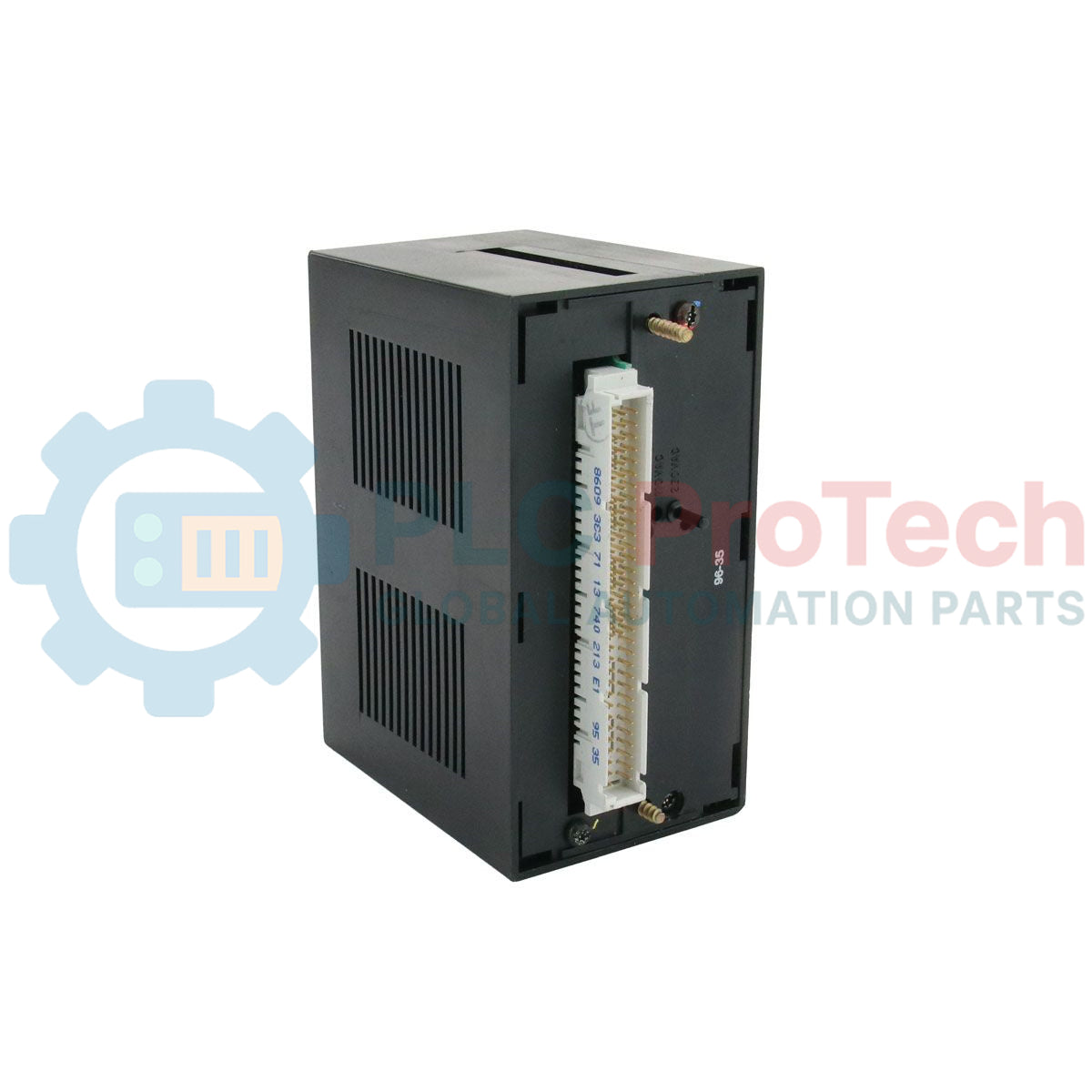
Refroidissement et circulation d’air : Étant donné ses dimensions compactes, ne bloquez pas les fentes de ventilation situées en haut ou en bas du boîtier. Maintenez au moins 20 mm de dégagement par rapport aux conduits de câblage adjacents pour assurer une convection passive qui maintient les composants internes dans la limite de 55 degrés Celsius.