Description fonctionnelle du système
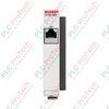
Le Beckhoff CX1010-N030 (CX1010-N030) est un module d’extension d’interface système série double canal dédié, conçu pour l’architecture matérielle modulaire CX1010 Embedded PC. Déployé largement dans les nœuds d’automatisation industrielle, les stations de surveillance environnementale à distance et les lignes centralisées de suivi des matériaux, ce module étend la connectivité physique du CPU principal. En fournissant des ports de communication matériels locaux dédiés, il décharge le traitement série de l’unité centrale, garantissant des temps d’exécution cycliques déterministes et évitant la perte de paquets de données lors de flux à haute vitesse.
Interconnexion matérielle et profil électrique
Cette interface système compacte s’insère dans le bus d’extension local, tirant son alimentation directement du bus système principal via la série de modules d’alimentation CX1100-xxxx en amont. L’interface physique offre deux canaux RS232 indépendants désignés COM1 et COM2, acheminés par deux connecteurs robustes D-sub mâles 9 broches. Capable de supporter des débits de transmission jusqu’à 115 kbaud, le matériel intègre des filtres anti-bruit pour préserver l’intégrité du signal face aux décharges électromagnétiques. Le module est conçu sous des contraintes architecturales strictes et ne peut pas être combiné sur la même pile avec les variantes d’interface N031 ou N041.
Matrice de performance technique
| Paramètre principal |
Spécification fonctionnelle |
| Numéro de modèle |
CX1010-N030 |
| Marque |
Beckhoff Automation |
| Origine |
Allemagne |
| Classification du composant |
Module d’extension série d’interface système |
| Ports de communication |
1 x COM1 + 1 x COM2 |
| Signalisation de l’interface physique |
Architecture série RS232 |
| Matériel de connexion |
2 x connecteurs D-sub, 9 broches mâles |
| Vitesse de transmission maximale |
115 kbaud |
| Limite de compatibilité du bus |
Non combinable avec les options N031 ou N041 |
| Infrastructure d’alimentation électrique |
Alimenté via le bus système (par les modules CX1100-xxxx) |
| Température de fonctionnement |
0 à +55 °C (sans condensation) |
| Température de stockage |
-25 à +85 °C |
| Humidité relative maximale |
95 %, sans condensation |
| Indice de protection contre les intrusions |
Module de type ouvert IP20 |
| Dimensions mécaniques (L x H x P) |
19 mm x 100 mm x 51 mm |
| Poids structurel net |
env. 80 g |
| Poids brut d’expédition |
2,0 kg (emballé en lot industriel volumineux) |
Diagnostics industriels et FAQ
Comment attribuez-vous les numéros de port COM dans TwinCAT si le système ne parvient pas à détecter l’interface série ?
Les blocs de configuration physique ne sont pas nécessaires. Ouvrez le logiciel TwinCAT System Manager, naviguez dans l'arborescence des périphériques I/O et scannez les tranches matérielles actives liées au nœud maître CX1010. Une fois détectées, le logiciel mappe automatiquement COM1 et COM2 aux registres internes correspondants des périphériques série. En cas d’échec du mappage, vérifiez que le module d’alimentation CX1100 en amont fournit un courant adéquat et que les contacts du bus sous-jacent sont exempts de contamination oxydée.
Pourquoi le manuel système indique-t-il que le CX1010-N030 ne peut pas être utilisé conjointement avec les modules N031 ou N041 ?
Le bus système interne sous-jacent du contrôleur CX1010 attribue des lignes d’adresse matérielle spécifiques et des registres d’interruption pour les extensions d’interface série externes. Les modules CX1010-N030 (RS232), N031 (RS422/RS485) et N041 (RS232 avec isolation) partagent des vecteurs d’adresse internes identiques. Tenter de verrouiller ces modules ensemble sur la même pile physique provoque un conflit de ressources matérielles, entraînant une erreur de démarrage du firmware et empêchant le runtime TwinCAT d’entrer en mode opérationnel.
Quels sont les principaux protocoles de dépannage en cas de corruption des données à la vitesse maximale de 115 kbaud ?
Les signaux RS232 utilisent des niveaux de tension asymétriques qui sont sensibles aux interférences électromagnétiques externes sur de longues distances. Assurez-vous d’abord que la longueur de connexion entre le connecteur D-sub 9 broches et le périphérique est bien inférieure à la longueur standard maximale de 15 mètres. Ensuite, vérifiez que la ligne série utilise un câble torsadé blindé de haute qualité et que le capot métallique du D-sub est en contact à faible impédance avec la plaque de masse de l’enveloppe.
Directives de mise en service et d'installation sur site
-
Engagement mécanique du segment de bus : Avant d’alimenter la baie du contrôleur, alignez les rails de guidage latéraux du CX1010-N030 avec l’interface gauche du PC embarqué CX1010 ou du module d’extension adjacent. Faites glisser l’unité droit vers l’arrière jusqu’à ce que les connecteurs internes du bus PC104 s’emboîtent fermement et que les clips de verrouillage mécaniques s’accrochent au rail DIN standard. Ne forcez pas le module en angle pour éviter d’endommager les broches de connexion internes de précision.
-
Couple de serrage des vis de retenue du connecteur D-Sub : Lors de la connexion du câble femelle 9 broches au connecteur D-sub du module, vérifiez l'alignement des broches pour éviter de les plier. Serrez uniformément les deux vis de retenue latérales intégrées à l'aide d'un tournevis de précision. Le verrouillage sécurisé de ces vis assure un soulagement continu des contraintes mécaniques, protégeant les soudures internes du module contre les vibrations mécaniques.
-
Gestion de l'Enveloppe Environnementale : Cette carte d'extension possède une classification IP20 et doit être installée dans une armoire de contrôle industrielle propre et scellée. Maintenez un espace libre d'au moins 30 mm au-dessus et en dessous de l'ensemble du module pour permettre un flux d'air convectif naturel. Retirez périodiquement toute poussière non conductrice ou particules environnementales accumulées dans les fentes de ventilation afin de garantir que l'unité fonctionne en toute sécurité dans sa plage thermique de 0 à +55 °C.