Présentation du produit
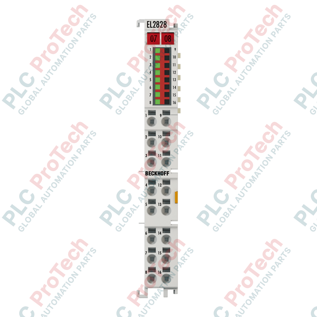
Le bornier EtherCAT EL2828 (EL2828) fournit huit sorties numériques protégées électroniquement fonctionnant à une tension nominale de 24 V CC. Utilisant une technologie avancée de connexion 2 fils, ce module Haute Densité (HD) est conçu pour piloter diverses charges, y compris des actionneurs ohmiques, inductifs et capacitifs.
Déployable dans des environnements industriels lourds — tels que l’emboutissage automobile, les lignes de tri automatisées et les installations d’emballage alimentaire — le module offre une capacité exceptionnelle de gestion de puissance. En supportant jusqu’à 2 A par canal individuel dans un format compact de 12 mm de large, le bornier élimine le besoin de relais d’interposition externes sur les charges à fort courant, optimisant l’espace dans l’armoire de commande et réduisant les points de défaillance pour éviter les arrêts système.
Protection électronique et caractéristiques de commutation
L’EL2828 dispose d’un circuit pilote interne robuste équipé d’une limitation du courant de court-circuit (limitant typiquement les défauts sous 40 A) et d’une protection native contre la tension inverse. Il est spécifié pour gérer une énergie de coupure inductive jusqu’à 1,2 J par canal, permettant la désactivation sécurisée des électrovannes et petites vannes CC sans diodes de roue libre externes.
La structure physique mappe un profil de sortie 8 bits directement dans l’image de processus cyclique EtherCAT E-bus, éliminant complètement l’adressage matériel manuel ou les paramètres de configuration logicielle. Sa vitesse de commutation très efficace présente un temps d’activation typique ($T_{ON}$) de 60 µs et un temps de désactivation ($T_{OFF}$) de 250 µs, facilitant un contrôle précis du timing pour des séquences d’automatisation rapides.
Caractéristiques techniques
| Paramètre |
Spécifications |
| Modèle |
EL2828 |
| Marque |
BECKHOFF |
| Origine |
Allemagne |
| Technologie E/S |
Bornier EtherCAT (communication E-bus) |
| Nombre de sorties |
8 sorties |
| Méthode de câblage |
Connexion 2 fils |
| Tension nominale de fonctionnement |
24 V CC (-15 % / +20 %) |
| Courant de sortie maximal |
2 A par canal (somme totale max 10 A) |
| Courant de court-circuit |
Typ. moins de 40 A |
| Énergie de coupure max |
Moins de 1,2 J par canal |
| Performance de commutation |
Typ. TON : 60 µs / Typ. TOFF : 250 µs |
| Protection contre la tension inverse |
Oui |
| Consommation de courant E-bus |
Typ. 110 mA |
| Consommation de courant des contacts de puissance |
Typ. 15 mA + courant de charge |
| Isolation galvanique |
500 V (E-bus vers potentiel terrain) |
| Largeur du bit de l’image de processus |
Sorties : 8 bits |
| Conception du boîtier |
Boîtier HD (Haute Densité) avec voyants d’état |
| Dimensions (L x H x P) |
12 mm x 100 mm x 68 mm |
| Poids |
Environ 70 g |
| Température de fonctionnement |
-25 à +60 °C (Installation verticale requise) |
| Température de stockage |
-40 à +85 °C |
| Indice de protection |
IP20 |
| Marquages de conformité |
CE, UL |
FAQ produit
Quels sont les avantages spécifiques de la technologie de connexion à 2 fils par rapport aux configurations standard à 1 fil ?
L’architecture à 2 fils fournit à la fois le signal de sortie 24 V CC et un point de retour de masse 0 V CC dédié pour chacun des huit canaux directement sur la face du bornier. Ce design simplifie le câblage en permettant aux actionneurs de terrain de se raccorder séquentiellement au module, éliminant ainsi les blocs de terminaison de masse externes à l’intérieur du panneau.
Comment la limite de courant total de 10 A restreint-elle le fonctionnement si tous les canaux peuvent tirer 2 A ?
Bien que chaque canal individuel puisse fournir jusqu’à 2 A en continu, les barres omnibus internes ont une limite physique maximale de 10 A. Cela signifie que si cinq canaux sont chargés à leur capacité maximale de 2 A ($5 \times 2\text{ A} = 10\text{ A}$), les trois canaux restants doivent rester inactifs pour ne pas dépasser le seuil de sécurité.
Ce module de terminaison utilise-t-il des horloges distribuées (DC) pour une commutation synchronisée ?
Non, l’EL2828 fonctionne sans horloges distribuées. Les commandes de commutation de sortie sont mises à jour et exécutées au niveau du module lors du cycle de trame immédiat suivant reçu du contrôleur maître EtherCAT.
Directives de terminaison sur le terrain et normes de sécurité
-
Protocoles de câblage à ressort HD : Ouvrez les points de connexion haute densité à l’aide d’un tournevis plat technique standard. Dénudez les fils de terrain sur une longueur de 8 à 9 mm. Les points de connexion acceptent du fil massif (s) de calibre AWG 28 à 16, du fil multibrins (st) de calibre AWG 22 à 16, ou des lignes isolées par embouts (f) de calibre AWG 26 à 19. Veillez à ce que les embouts soient sertis bien carrés pour garantir une prise mécanique durable.
-
Verrouillage mécanique et dissipation thermique : Montez le module verticalement sur un rail DIN standard de 35 mm conforme à la norme EN 60715. Assurez-vous que la double fente de verrouillage et les points de connexion à clé s’enclenchent fermement avec les unités adjacentes pour établir un contact continu sur le dos du rail. L’orientation verticale est obligatoire ; en charge maximale de 10 A et à haute température ambiante, un flux d’air actif sur le panneau est nécessaire pour rester dans la plage de fonctionnement de -25 à +60 °C.
-
Gestion des transitoires inductifs : Bien que l'EL2828 intègre un circuit de suppression évalué à moins de 1,2 J, la commande régulière de charges inductives importantes ou de solénoïdes à cycle de service élevé peut entraîner une accumulation thermique. Pour les grandes bobines de champ, il est fortement recommandé de monter une diode de roue libre externe aux bornes de l'actionneur afin de supprimer les pics de tension inverse directement à la source.