Description
Processing precise differential 1 VPP signals for high-performance motion feedback, the Beckhoff EL5021-0090 EtherCAT Terminal incorporates integrated TwinSAFE SC (Single Channel) technology to enable safety-related data transmission in standard control environments. This terminal interfaces seamlessly with high-resolution SinCos encoders, utilizing a 70 MHz internal scanning system to process input frequencies up to 250 kHz with a max resolution of 13 bits per period. Built-in error detection flags signal degradation, amplitude faults, and frequency boundaries, allowing for real-time diagnostic visibility directly within the TwinCAT architecture.
Features
-
TwinSAFE SC Support: Allows the use of standard analog signal sources for safety-directed tasks up to PL d/Category 3 or SIL 2.
-
High-Resolution Tracking: Max 13-bit resolution providing up to 8192 steps per signal period.
-
Advanced Diagnostics: Built-in hardware detection for amplitude and frequency errors, latch, and counter reset functions.
-
Synchronized Execution: Distributed Clocks (DC) support ensures highly precise microsecond-level synchronization across the EtherCAT network.
-
Integrated Signal Conditioning: Generates a stable 5 V DC encoder supply (up to 0.5 A) directly from the 24 V DC power contacts.
Applications
- High-speed servo axis position feedback in multi-axis machinery.
- Safety-related speed and direction monitoring (TwinSAFE SC architectures).
- Precision positioning systems on CNC lathes, milling machines, and gantries.
- Dynamic material testing equipment requiring microsecond feedback loops.
Technical Specifications
| Parameter |
Specification |
| Manufacturer |
Beckhoff Automation |
| Model / Article Number |
EL5021-0090 |
| Technology |
SinCos encoder interface for differential 1 VPP signal |
| Number of Channels |
1 |
| Encoder Interface Inputs |
1 x A, B, C: differential inputs 1 VPP: A, A (inv), B, B (inv), C, C (inv) |
| Encoder Operating Voltage |
5 V DC / max. 0.5 A (derived from 24 V DC power contacts) |
| Counter Range |
Max. 24 bit (adjustable) |
| Input Frequency |
250 kHz (internal scanning of input signals at 70 MHz) |
| Nominal System Voltage |
24 V DC (-15% / +20%) |
| Resolution |
Max. 13 bit, 8192 steps per period |
| Current Consumption (E-Bus) |
Typically 120 mA |
| Current Consumption (Power Contacts) |
Typically 50 mA + encoder load |
| Distributed Clocks (DC) |
Yes, supported |
| Electrical Isolation |
500 V (E-bus / field potential) |
| Operating Temperature |
0 to +55 degC |
| Storage Temperature |
-25 to +85 degC |
| Vibration/Shock Resistance |
Conforms to EN 60068-2-6 / EN 60068-2-27 |
| EMC Immunity/Emission |
Conforms to EN 61000-6-2 / EN 61000-6-4 |
| Approvals & Markings |
CE, UL, ATEX (II 3 G Ex nA IIC T4 Gc) |
| Dimensions (W x H x D) |
12 mm x 100 mm x 68 mm |
| Connection Cross-Section (AWG) |
Solid/Stranded: AWG 28...14; Ferrule: AWG 26...16 |
| Net Weight |
Approximately 55 g |
| Shipping Weight (Calculated) |
2.0 kg (with protective export packaging) |
| Country of Origin |
Germany |
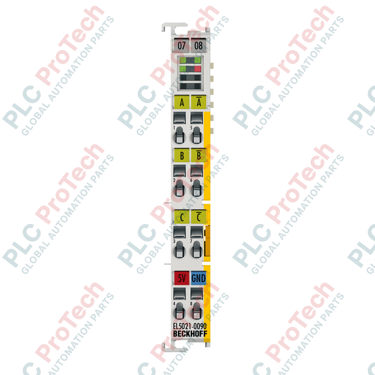
Connections and Interfaces
| Terminal Point |
Signal Name |
Function / Description |
| 1 |
A + |
Positive differential input channel A (1 VPP) |
| 2 |
B + |
Positive differential input channel B (1 VPP) |
| 3 |
C + |
Positive differential input channel C / Zero pulse (1 VPP) |
| 4 |
+5 V Out |
Encoder power supply output (+5 V DC, max. 0.5 A) |
| 5 |
A - |
Negative differential input channel A (1 VPP) |
| 6 |
B - |
Negative differential input channel B (1 VPP) |
| 7 |
C - |
Negative differential input channel C / Zero pulse (1 VPP) |
| 8 |
0 V Out |
Encoder power supply ground (0 V DC) |
Empirical Engineering Insights
Alternative Models & Compatibility
The EL5021-0090 acts as the safety-enhanced alternative to the standard EL5021-0000. While they share identical physical dimensions and signal wiring assignments, the -0090 contains TwinSAFE SC logic. Integrating the EL5021-0090 into an existing system requires mapping the safety process data objects (PDOs) inside TwinCAT 3 (using the TwinSAFE SC helper protocol). If a direct drop-in replacement is performed on a system where standard TwinSAFE SC parameters are not declared in the project, the PLC will fail to initialize the EtherCAT state machine beyond Pre-OP due to XML device description mismatches.
Application Pitfalls & Engineering Notes
E-Bus Current Allocation: The EL5021-0090 has a high E-bus current draw of 120 mA. When grouping multiple high-speed encoder interfaces on a single EK1100 coupler, you must calculate the total E-bus current. If the cumulative load exceeds 2 A, a secondary power feed terminal (such as EL9410) must be added immediately before the encoder modules to prevent voltage drops on the E-bus and subsequent bus interruption faults.
Signal Attenuation: 1 VPP differential signals are highly susceptible to noise over long distances. High-frequency operations (>150 kHz) require low-capacitance, double-shielded twisted-pair cabling. Keep distances between the encoder and the terminal under 20 meters; longer lengths risk triggering "Amplitude Error" diagnostics in the TwinCAT status word.
Commissioning & Wiring Tips
To bypass noise-induced commissioning errors, verify that the encoder cable shield is terminated to an earth-ground bar immediately before entering the terminal block. Avoid running the 1 VPP encoder cables parallel to high-power motor power cables inside the wire ducting. When commissioning in TwinCAT, activate the diagnostic PDOs to monitor the Amplitude Error and Frequency Error flags. This allows on-site technicians to diagnose mechanical encoder misalignments or bad cable terminations before putting the axis into operation.
Installation Guidelines
CRITICAL WARNING
De-energize all 24 V DC power contacts and the main E-bus supply before installing, removing, or wiring the terminal. Inserting or removing the EL5021-0090 under load can damage the internal E-bus transceiver chips and corrupt the TwinSAFE SC safety validation state in the safety group.
1
DIN Rail Mounting: Position the terminal on a standard 35 mm DIN rail (conforming to EN 60715) and push down firmly until the locking slide clicks onto the rail. Ensure the side-by-side key and slot connection fits snugly with neighboring terminals.
2
Shield Connection: Run the encoder shield directly to an adjacent EL9195 or standard shield clamp terminal connected to the DIN rail to guarantee low-impedance high-frequency noise diversion.
3
Wiring the Spring Clamps: Insert a standard flathead screwdriver into the upper square release slot of the clamp, insert the stripped wire (stripping length 8 to 9 mm) into the circular feed, and release the screwdriver to lock.