Description
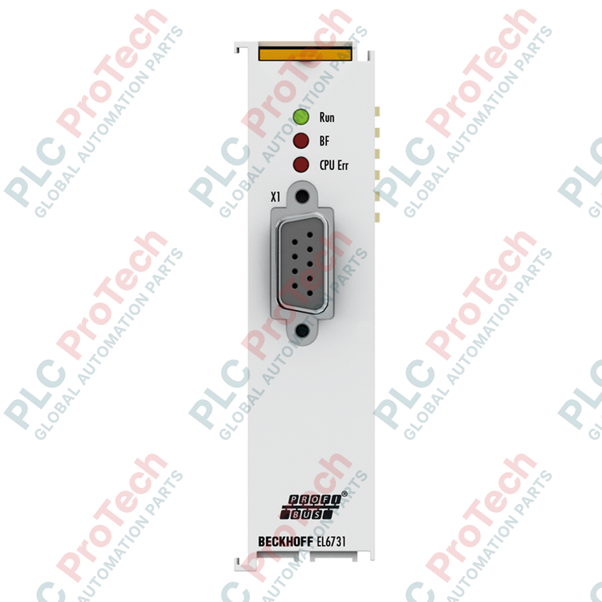
To integrate standard legacy fieldbus communication into modern control networks, the Beckhoff EL6731-0010 acts as a dedicated PROFIBUS DP slave terminal within the modular EtherCAT Terminal system. This compact terminal enables direct communication between an EtherCAT network master and any upstream PROFIBUS DP master controller. Incorporating an optimized, non-volatile memory structure, the device offers highly flexible cyclic data exchange capacities, accommodating process images up to 1.4 kbytes of input and 1.4 kbytes of output data. By mapping PROFIBUS diagnostics, configuration parameters, and alarm states directly to the EtherCAT process image, it ensures high diagnostic transparency and seamless cross-platform control synchronization.
Features
-
Multi-Protocol Support: Seamlessly processes PROFIBUS DP, DP-V1 (Class 1 and 2 acyclic services, alarms), DP-V2, and equidistant PROFIBUS MC configurations.
-
Broad Baud Rate Spectrum: Auto-detects and supports transmission rates ranging from 9.6 kbaud up to 12 Mbaud.
-
Galvanic Isolation: Embedded 1 x D-sub 9-pin interface is galvanically isolated to guard the internal E-bus circuitry from fieldbus transient noise.
-
CDL Concept Capability: Supports differing DP cycle times per slave using standard control data link technology.
-
Integrated Status Diagnostics: Onboard LED indicators display real-time physical layer, protocol, and connection health.
Applications
-
Legacy PLC Integration: Linking legacy Siemens S7 or third-party PROFIBUS DP master PLCs into central Beckhoff EtherCAT networks.
-
Distributed Control Architecture: Bridging secondary conveyor lines, processing skids, or paint booths equipped with PROFIBUS field devices into an EtherCAT ring topology.
-
Process Industry Automation: Integrating hazardous-area standard process instruments using DP-V1/DP-V2 diagnostic profiles.
Technical Specifications
| Specification |
Value |
| Manufacturer |
Beckhoff Automation |
| Model Number |
EL6731-0010 |
| Fieldbus Type |
PROFIBUS DP, DP-V1, DP-V2, PROFIBUS MC |
| Data Transfer Rates |
9.6 kbaud to 12 Mbaud |
| Interface Type |
1 x D-sub socket, 9-pin, galvanically decoupled |
| Process Image Memory |
Max. 1.4 kbyte input / 1.4 kbyte output data |
| E-bus Current Consumption |
Typical 350 mA |
| Operating Temperature |
-25 to +60 degC (no condensation) |
| Storage Temperature |
-40 to +85 degC |
| Dimensions (W x H x D) |
24 mm x 100 mm x 52 mm |
| Housing Material |
Polycarbonate (compact terminal housing) |
| Protection Class |
IP20 |
| Environmental Standards |
Conforms to EN 60068-2-6 (Vibration) and EN 60068-2-27 (Shock) |
| Approvals & Markings |
CE, UL, ATEX (II 3 G Ex nA IIC T4 Gc) |
| Net Weight |
70 g |
| Shipping Weight (Calculated) |
0.25 kg |
Connections and Interfaces
| D-Sub 9-Pin Connector |
Signal Assignment |
Description |
| Pin 3 |
RxD/TxD-P |
Receive/Transmit Data - Positive (B-Line, Red) |
| Pin 5 |
DGND |
Data Ground (Reference potential for VP) |
| Pin 6 |
VP |
Supply Voltage Plus (+5V for terminating resistors) |
| Pin 8 |
RxD/TxD-N |
Receive/Transmit Data - Negative (A-Line, Green) |
| Metal Frame |
Shield |
Functional Earth Shielding Connection |
Empirical Engineering Insights
Alternative Models & Compatibility
Do not confuse the EL6731-0010 (Slave module) with the standard EL6731 (Master/Scanner module). While both share the same physical 24 mm housing, their firmware profiles are entirely different. The EL6731-0010 is addressed in TwinCAT exclusively as an EtherCAT-to-PROFIBUS slave box, requiring a GSD file for configuration on the upstream master controller.
Application Pitfalls & Engineering Notes
Since this terminal lacks physical rotary switches for manual PROFIBUS slave address setting, the node address must be assigned programmatically through the TwinCAT System Manager via the EtherCAT CoE (CoE index 0xF800:01) or standard GSD assignment. If using multiple high-draw communication cards on a single E-bus rail segment, carefully track your cumulative E-bus current. The EL6731-0010 draws a substantial 350 mA, meaning you may need an EL9410 power supply booster terminal on the right-hand side of the segment to avoid voltage drops.
Commissioning & Wiring Tips
To prevent high-frequency reflections and transmission errors, ensure that standard active RS485 termination is enabled at the end of the physical PROFIBUS line. The internal DB9 port of the EL6731-0010 provides +5V (Pin 6) and DGND (Pin 5) to supply a standard active termination connector. Always ground the DIN rail reliably to allow the terminal's rear grounding contact spring to discharge electrical noise efficiently.
Installation Guidelines
CRITICAL WARNING
Disconnect the entire 24V DC bus and E-bus control power supplies before sliding, inserting, or removing the EL6731-0010 terminal. Failure to do so can cause electrostatic damage or permanently damage the internal E-bus contacts of neighboring EtherCAT terminals.
1
Align the EL6731-0010 on the 35 mm DIN rail (EN 60715) alongside your existing EtherCAT coupler or processor terminal.
2
Press the module firmly onto the rail until the latching locking mechanism clicks securely, ensuring continuous electrical contact of the rear E-bus terminal pins.
3
Insert the standard shielded 9-pin D-sub PROFIBUS connector and secure its retaining screws to minimize vibration susceptibility.
4
Turn on system power, scan the network inside TwinCAT, and verify that the physical state LEDs indicate proper communication synchrony.