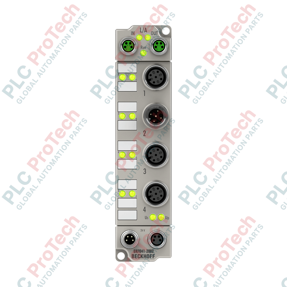
Description
Decentralized motion control in demanding physical environments is directly addressed by the Beckhoff ER7041-2002 EtherCAT Box, a heavy-duty, IP67-rated module engineered for the direct connection of 2-phase stepper motors. Operating within an extensive voltage envelope of 8 to 48 V DC, this unit integrates a localized control system with feedback capabilities, reducing the physical footprint in control cabinets by moving power electronics directly onto the machine chassis. It features a continuous current output of 2 x 3.5 A and can withstand short-duration peak surges up to 2 x 5 A, with robust overload and short-circuit protections. By utilizing 64-fold microstepping and an integrated 24 V DC encoder interface, the module provides closed-loop control, mitigating step-loss and ensuring exact positioning accuracy under varying load conditions.
Features
-
Closed-Loop Positioning: Dedicated 24 V DC encoder interface for real-time axis verification.
-
Advanced Microstepping: Supports up to 64-fold microstepping to ensure low-vibration and quiet motor operations.
-
Ruggedized Construction: Encased in an IP65/66/67 sealed housing resistant to dust, moisture, and high-pressure washdowns.
-
Integrated Digital I/O: Features 2 digital inputs (24 V DC) for direct connection of limit switches or reference sensors.
-
High Peak Current Capacity: Delivers up to 5 A peak current per phase to handle high-inertia breakaway loads.
-
Synchronized Operation: Built-in Distributed Clocks (DC) support for microsecond-precise coordination across the EtherCAT network.
Applications
-
Field-Level Motion Control: Decentralized drive axes on conveyor tracks, sorting tables, and processing lines.
-
Packaging & Bottling: Feed systems, labeling stations, and volumetric pumps operating in high-moisture or washdown zones.
-
Assembly & Material Handling: Localized pick-and-place coordinate gantries and indexer plates.
Technical Specifications
| Manufacturer |
Beckhoff Automation |
| Model/Article Number |
ER7041-2002 |
| Fieldbus Protocol |
EtherCAT |
| Bus Interface |
2 x M8 socket, shielded, screw-lock type |
| Motor Connection Type |
M12 x 1, 5-pin, A-coded |
| Supported Load Type |
2-phase stepper motor (unipolar or bipolar) |
| Nominal Supply Voltage |
8 to 48 V DC (via external power contact) |
| Output Current |
2 x 3.5 A continuous; 2 x 5 A peak (overload/short-circuit proof) |
| Control Frequency |
30 kHz current controller frequency |
| Step Resolution |
64-fold microstepping (configurable) |
| Electrical Isolation |
500 V (control voltage / power voltage) |
| Current Consumption (US) |
120 mA from EtherCAT system voltage |
| Operating Temperature |
-25 to +60 degC |
| Storage Temperature |
-40 to +85 degC |
| Ingress Protection Rating |
IP65/66/67 (conforms to EN 60529) |
| Compliance & Approvals |
CE, EN 61000-6-2 (Immunity), EN 61000-6-4 (Emission) |
| Weight |
265 g |
| Shipping Weight (Calculated) |
2.0 kg |
Connections and Interfaces
| Port Type |
Connection Method & Pin Assignment |
| EtherCAT Input |
M8 socket, 4-pin, shielded (receives communication frame) |
| EtherCAT Output |
M8 socket, 4-pin, shielded (forwards communication to next node) |
| Motor & Sensor Port |
M12 socket, 5-pin, A-coded (assigned to motor phases A/B, digital inputs) |
| Power Supply |
M8 plug, 4-pin (US system voltage: 24 V DC; UP load voltage: 8 to 48 V DC) |
Empirical Engineering Insights
Alternative Models & Compatibility
The ER7041-2002 functions as the IP67 hardened variant of the standard Beckhoff EL7041 DIN-rail terminal. Both devices utilize the same underlying CoE (CAN over EtherCAT) object dictionary structures (primarily index 0x8010 for configuration), allowing control code written for the EL7041 to be migrated directly to the ER7041-2002. However, engineers must account for different physical pinouts on the M12 circular connectors compared to the spring-clamp terminal block of the EL series.
Application Pitfalls & Engineering Notes
Thermal performance is highly dependent on mounting configuration. When driving a motor continuously near the 3.5 A limit, the zinc die-cast housing must be mounted flat against a metallic, thermally conductive machine frame to act as a natural heat sink. If mounted on non-conductive surfaces or composite brackets in ambient temperatures exceeding 45 degC, the module is susceptible to internal thermal overload shutdowns, throwing CoE fault codes associated with driver overtemperature.
Commissioning & Wiring Tips
To prevent inductive kickback spikes from damaging the internal output stage, the motor power supply line (UP) must be properly decoupled. If using long cable runs (exceeding 10 meters) between the module and the stepper motor, shielded twisted-pair cables must be utilized, with the shield terminated directly to the M12 connector housing to minimize high-frequency electromagnetic emissions generated by the 30 kHz PWM chopper circuit.
Installation Guidelines
CRITICAL WARNING
Do not connect or disconnect any M12 or M8 cables while the system is energized. Breaking connection under load can induce severe back-EMF voltage transients, causing permanent dielectric breakdown of the motor driver MOSFETs.
1
Mount the module to a flat, vibration-resistant machine frame using M4 bolts. Maximize metal-to-metal contact to aid in thermal dissipation.
2
Connect the EtherCAT input and output cables using shielded M8 screw-lock connectors, ensuring a torque of 0.4 Nm is applied to preserve the IP67 moisture seal.
3
Configure the stepper motor phase currents inside the TwinCAT System Manager CoE list before enabling the axis. Setting the holding and run currents incorrectly can cause immediate motor overheating.