Description
Operating as a specialized interface within the Beckhoff I/O system, the Beckhoff ES2521 EtherCAT Terminal delivers precise pulse train signals for motion control applications. This high-performance module converts 16-bit velocity values from the automation controller into a highly accurate RS422 differential frequency output. Capable of generating base frequencies from 0 to 500 kHz, it is engineered to interface directly with stepper motor drivers, servo drives, and frequency converters that accept frequency/direction or pulse train control commands. The unit features built-in distributed clocks support for precise, synchronized operation across multi-axis networks, and incorporates a pluggable wiring design that simplifies field installation and cabinet maintenance.
Features
-
1-Channel Pulse Train Control: Equipped with two differential RS422 outputs (Signals A and B) for high-speed pulse and direction generation.
-
Flexible Operating Modes: Configurable via the controller to support pulse/direction output, count pulses with frequency limits, or operate under direct frequency selection.
-
High-Frequency Resolution: Offers a base frequency range from 0 to 500 kHz with a fine step resolution of 10 mHz for smooth acceleration ramps.
-
Integrated Controller Functions: Supports autonomous ramp execution and precise travel distance control natively within the hardware profile.
-
Pluggable Wiring Interface: Uses the ESxxxx plug-in connector system for tool-free assembly, rapid module replacement, and secure terminal connection.
-
Distributed Clocks (DC): Ensures sub-microsecond synchronization with other EtherCAT devices on the segment for highly coordinated motion profiles.
-
Comprehensive Diagnostics: LED indicators supply real-time statuses for state transition, communication activity, and specific channel errors.
Applications
- Direct speed control of stepper motor power stages accepting RS422 pulse train commands.
- Interfacing with servo drives configured for pulse-and-direction positioning modes.
- Commanding variable frequency drives (VFDs) requiring high-resolution frequency references.
- Precision positioning tasks in packaging machinery, pick-and-place systems, and material handling systems.
Technical Specifications
| Parameter |
Specification Value |
| Manufacturer |
Beckhoff |
| Model Number |
ES2521 |
| Connection Technology |
Pulse train (frequency output) with pluggable wiring harness |
| Number of Channels |
1 channel (consisting of 2 differential outputs: A, B) |
| Digital Inputs |
2 inputs (+T Latch, +Z Gate) |
| Input Signal Voltage |
24 V DC |
| Output Signal Specification |
RS422 levels, differential |
| Output Current Limit |
Maximum 50 mA per channel (short-circuit proof) |
| Base Frequency Range |
0 to 500 kHz (Default configuration: 50 kHz) |
| Output Resolution |
Max. 15 bit |
| Frequency Step Size |
10 mHz |
| Process Image Width |
14-byte output, 8-byte input |
| Current Consumption E-bus |
Typically 280 mA (load-dependent) |
| Current Consumption Power Contacts |
No current draw from external power contacts |
| Electrical Isolation |
500 V RMS (E-bus to field potential) |
| Operating Temperature |
0 to +55 degC |
| Storage Temperature |
-25 to +85 degC |
| Relative Humidity |
95% non-condensing |
| Protection Rating |
IP20 |
| Hazardous Location Approvals |
ATEX: II 3 G Ex ec IIC T4 Gc, IECEx: Ex ec IIC T4 Gc |
| Net Weight |
Approximately 50 g |
| Shipping Weight (Calculated) |
2.0 kg |
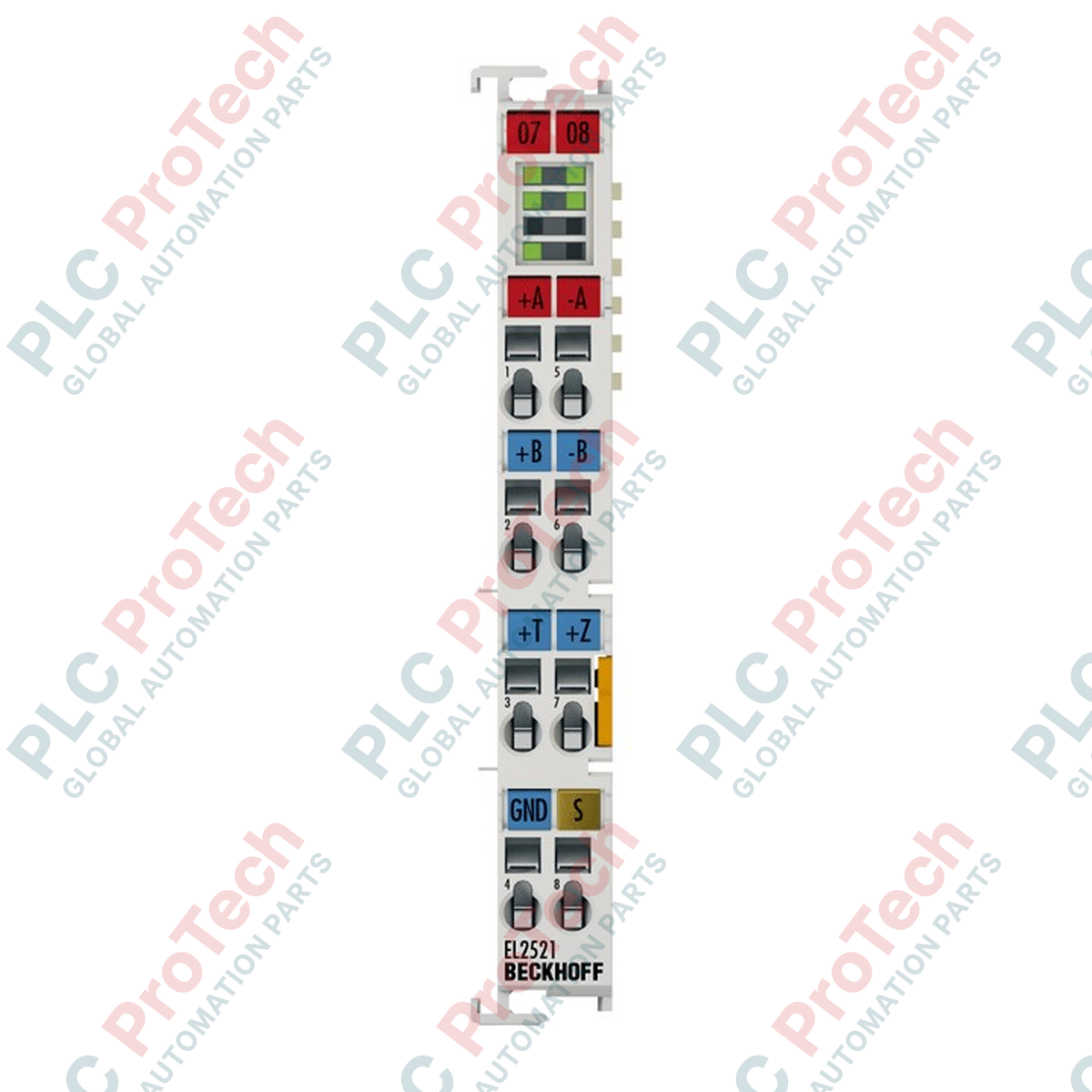
Connections and Interfaces
| Terminal Connection Point |
Signal Assignment |
Description |
| Pin 1 |
Output A |
Non-inverted differential output channel A (Pulse / Frequency) |
| Pin 5 |
Output /A |
Inverted differential output channel A |
| Pin 2 |
Output B |
Non-inverted differential output channel B (Direction) |
| Pin 6 |
Output /B |
Inverted differential output channel B |
| Pin 3 |
Input +T |
Latch input (24 V DC) for high-speed hardware position capture |
| Pin 7 |
Input +Z |
Gate / zero input (24 V DC) for axis reference calibration |
| Pin 4 |
+24 V DC |
Control power supply input for the digital logic |
| Pin 8 |
0 V DC (GND) |
Reference potential for inputs and external drive circuits |
Alternative Models & Compatibility
The ES2521 and the EL2521 share identical process images, register configurations, and TwinCAT device descriptions. The sole distinction lies in the physical connector style: the ES2521 features a pluggable wiring block, enabling off-terminal wire terminations and swift physical component replacement, whereas the EL2521 incorporates standard direct-in push-in termination. System integrators can seamlessly interchange the modules in TwinCAT without requiring configuration modifications, provided the plug-in connector harness is deployed.
Application Pitfalls & Engineering Notes
A key layout consideration is the high internal E-bus current consumption of the module. Consuming 280 mA typical from the communication backplane, the ES2521 is highly power-intensive. When constructing an EtherCAT segment containing multiple high-draw interfaces, the aggregate current must not exceed the maximum supply capability of the coupler (often capped at 2000 mA). If the E-bus power budget is breached, intermittent communication drops or localized terminal failures will manifest. Insert a dedicated power feed terminal (such as the EL9400 or EL9410) directly upstream of the module to resolve backplane load issues.
Commissioning & Wiring Tips
To protect signal integrity up to the full 500 kHz switching threshold, always employ shielded, twisted-pair cabling for the A/A and B/B differential lines. For optimal electromagnetic compatibility, terminate the cable shields as close as possible to the terminal entry point inside the enclosure using functional earth grounding clamps. Unshielded runs or running signal lines in parallel with motor power outputs will induce electrical noise, resulting in positioning inaccuracies or cumulative pulse count slippage over extended operational cycles.
Installation Guidelines
CRITICAL WARNING
Isolate all electrical power sources supplying the DIN rail assembly and field devices before commencing terminal installation or removal. Working under active voltage introduces short-circuit risks that can destroy the precision logic cards on the E-bus and permanently damage connected motor control inputs.
1
Verify that the selected terminal segment provides sufficient E-bus power capacity, accounting for the module's baseline 280 mA rating.
2
Securely latch the terminal housing onto the 35 mm DIN rail (EN 60715) ensuring the side E-bus slide contacts mate flush with the neighboring unit.
3
Pre-wire the pluggable wiring block with the appropriate conductor cross-sections (0.08 to 2.5 mm2) before snapping the connector plug firmly into the module socket.
4
Energize the backplane power supply and activate TwinCAT to scan for the new terminal, applying necessary axis-control parameters via the configuration tree.