Description
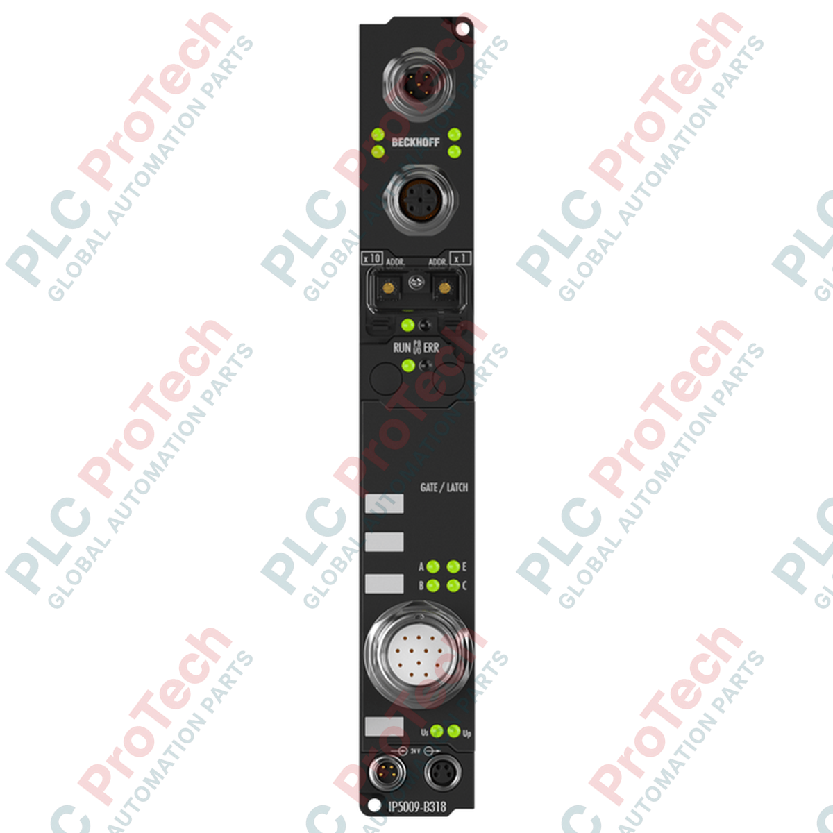
Decentralized acquisition of high-frequency sensor data is directly enabled by the Beckhoff IP5009-B318, an IP67-rated PROFIBUS DP Fieldbus Box designed for harsh operating environments. This module interfaces absolute encoders or displacement sensors utilizing the SSI (Synchronous Serial Interface) protocol, transferring data directly to the higher-level master controller via PROFIBUS DP. With integrated B-coded M12 connections acting as a built-in T-connector, the module allows for direct bus line looping without requiring external active junctions. Configuration and parameters can be easily adjusted using the KS2000 software tool or directly via controller-driven DP-V1 acyclic slot communication.
Features
-
PROFIBUS DP Compatibility: Complete support for baud rates up to 12 Mbaud with integrated automatic speed detection.
-
Rugged Enclosure Design: Full IP65, IP66, and IP67 protection ratings, eliminating the need for protective control cabinets in the field.
-
Integrated Loop-Through: M12 male and female B-coded interfaces enable simple daisy-chaining of the fieldbus line.
-
Flexible Configuration: Supports DP-V1 communication extensions for dynamic, runtime parameter adjustments.
-
Reliable Power Distribution: Standardized M8 connectors for control voltage and downstream load distribution.
Applications
- Decentralized SSI absolute encoder feedback in packaging and material handling systems.
- High-accuracy position sensing on outdoor linear axes and heavy machinery.
- Automotive assembly lines requiring direct, field-mounted sensor integration.
- Wind turbine pitch control systems and waste-water treatment plants.
Technical Specifications
| Parameter |
Value |
| Manufacturer |
Beckhoff |
| Model Number |
IP5009-B318 |
| Fieldbus Protocol |
PROFIBUS DP (with DP-V1 support) |
| Data Transfer Rates |
Up to 12 Mbaud (automatic detection) |
| Fieldbus Interface |
1 x M12 socket (5-pin), 1 x M12 plug (5-pin), B-coded |
| Control Voltage Supply |
24 V DC (-15% / +20%) |
| Current Consumption (Box Supply) |
85 mA + sensor load (max. 0.5 A) |
| Power Feed / Downstream |
1 x M8 male socket (4-pin) / 1 x M8 female socket (4-pin) |
| Isolation (Control / Fieldbus) |
None (electrical isolation is determined by sensor configuration) |
| Cycle Time |
Approx. 0.5 ms (for typical network of 10 boxes with 32-bit I/O each) |
| Operating Temperature |
0 to +55 degC |
| Storage Temperature |
-25 to +85 degC |
| Protection Rating |
IP65 / IP66 / IP67 (conforms to EN 60529) |
| Vibration/Shock Resistance |
Conforms to EN 60068-2-6 / EN 60068-2-27 |
| Approvals |
CE, UL |
| Shipping Weight (Calculated) |
2.0 kg |
Connections and Interfaces
| Interface Connection |
Pin Number |
Signal Assignment |
| PROFIBUS DP M12 (B-coded) |
Pin 1 |
VP (+5 V DC for active termination) |
| Pin 2 |
RxD/TxD-N (A-line, Green) |
| Pin 3 |
DGND (Data Ground) |
| Pin 4 |
RxD/TxD-P (B-line, Red) |
| Pin 5 |
Shield |
| Power M8 (Feed Connection) |
Pin 1 |
+24 V DC control voltage (Us) |
| Pin 2 |
+24 V DC load voltage (Up) |
| Pin 3 |
GND (Us) |
| Pin 4 |
GND (Up) |
Alternative Models & Compatibility
The IP5009-B318 replaces several legacy non-coupled configurations by bringing SSI decoding down to the machine level. Ensure your GSD file is updated to include the exact module parameters to prevent cyclic data exchange errors with older master systems. For setups utilizing the EtherCAT network topology rather than PROFIBUS, the EP5001-0002 serves as the native EtherCAT fieldbus equivalent.
Application Pitfalls & Engineering Notes
When daisy-chaining multiple boxes via the M8 power distribution interfaces, calculate the total voltage drop. The cumulative control current (Us) should not exceed 4 A across a single segment to prevent high thermal stress on the internal bus rails. Since control voltage and fieldbus communications do not share electrical isolation inside the module, run all system fieldbus lines in separated, shielded trays to prevent EMI-induced communication dropouts.
Commissioning & Wiring Tips
For optimal performance, use a terminating resistor if the IP5009-B318 acts as the physical last node in the PROFIBUS segment. Standard active termination can be accomplished using an M12 B-coded terminator connected to the downstream socket interface. Ensure the SSI sensor cable is shielded and connected directly to the designated housing shield collar to maintain signal integrity during dynamic motor acceleration cycles.
Installation Guidelines
CRITICAL SAFETY WARNING
Isolate all electrical power sources before initiating installation, removal, or wiring processes. Verify that both control and load voltages (Us and Up) are fully de-energized. Failure to strictly follow these safety steps can cause immediate physical danger or catastrophic failures to connected high-precision SSI sensors.
1
Mount the Fieldbus Box on a flat, vibration-free surface using two M4 mounting screws.
2
Securely torque the M12 B-coded PROFIBUS cable connectors to prevent moisture and dust ingress.
3
Wire the M8 power supply connection, ensuring polarity matches for both control (Us) and load (Up) segments.
4
Verify connection status and baud rate sync via the diagnostic LEDs prior to running system processes.