Description
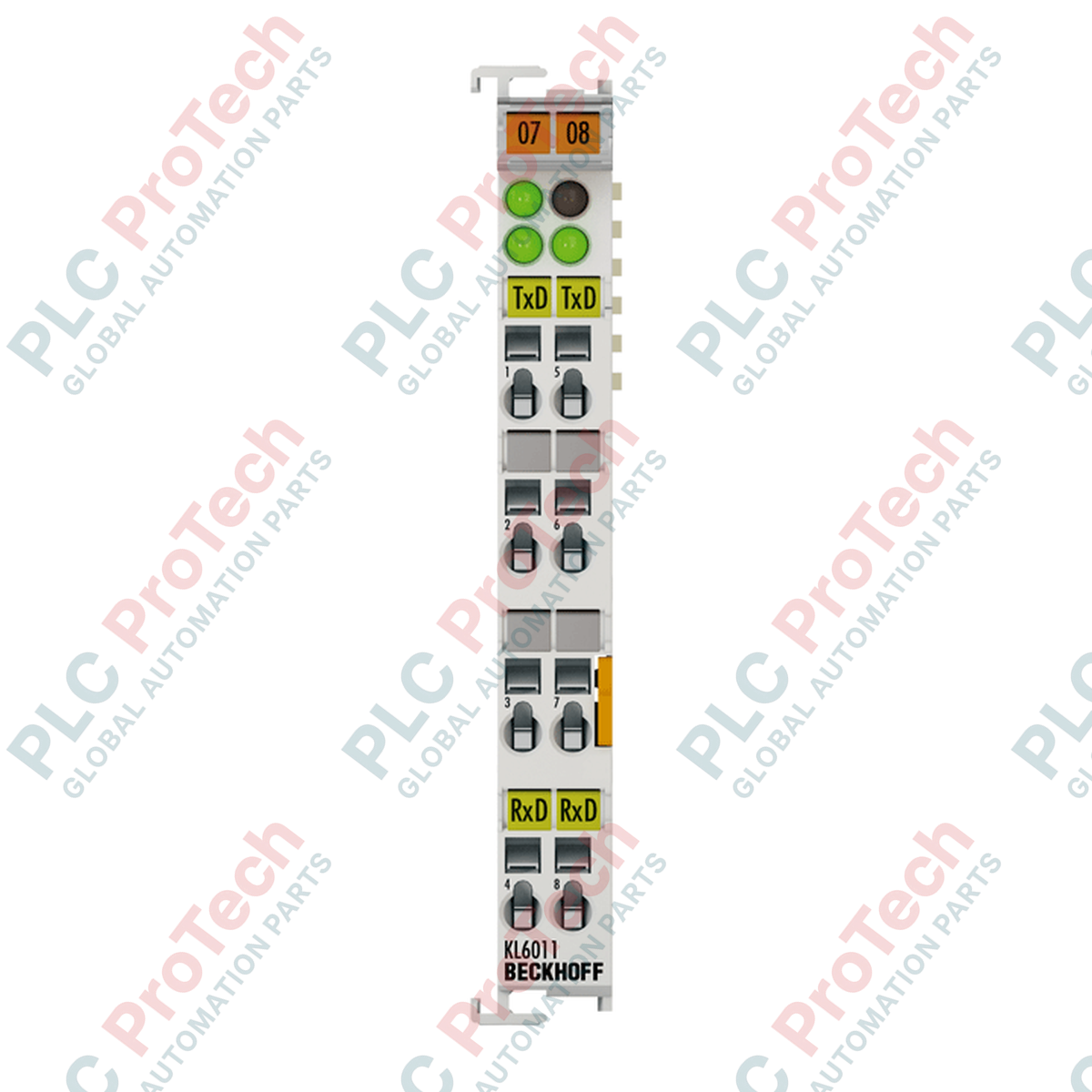
Integrating serial communication directly into the Beckhoff I/O system, the Beckhoff KL6011 serial interface terminal enables connection to devices equipped with a 20 mA current loop (TTY) interface. The terminal operates fully independently of the higher-level bus system, executing bidirectional transmission of data channels (TxD and RxD) in full duplex mode. The active or passive status of the current loop can be established through external wiring configurations, ensuring high adaptability to legacy serial interfaces, industrial weighing systems, and long-distance terminal connections up to 1000 meters.
Features
-
Active/Passive Flexibility: Configurable 2 x 20 mA active or passive current loops to interface with various sender/receiver architectures.
-
Configurable Baud Rates: Supports transfer rates ranging from 1200 baud up to 19,200 baud to match legacy serial peripherals.
-
Integrated Data Buffering: Equipped with a 128-byte receive buffer and a 16-byte transmit buffer to handle temporary data peaks without processing loss.
-
K-Bus Galvanic Isolation: Provides robust 500 V electrical isolation between the internal K-bus and the field-side signal paths to safeguard control networks.
-
Variable Process Image: Flexible bit-width configuration in the process image (from 3 x 8-bit to 5 x 8-bit user data plus control/status byte).
Applications
-
Legacy Peripheral Integration: Connecting older industrial printers, barcode readers, and display terminals to modern EtherCAT/K-bus architectures.
-
Industrial Weighing Systems: Direct communication with load cells and digital balances that rely on 20 mA current loops.
-
Long-Distance Serial Links: Point-to-point serial communication up to 1000 meters in high-noise environments where RS232 is ineffective.
Technical Specifications
| Parameter |
Specification Value |
| Manufacturer |
Beckhoff |
| Model / Article Number |
KL6011 |
| Interface Type |
TTY (20 mA current loop) |
| Number of Channels |
2 (1 transmit TxD, 1 receive RxD), full duplex |
| Data Transfer Rates |
1200 to 19,200 baud (Default: 9600 baud, 8 data bits, no parity, 1 stop bit) |
| Bit Transfer Current |
2 x 20 mA |
| Loop Resistance (Load) |
Less than 500 ohms |
| Cable Length |
Max. 1000 m shielded twisted pair |
| Power Supply |
Via the internal K-bus |
| Current Consumption (K-bus) |
Typical 55 mA |
| Electrical Isolation |
500 V (K-bus to signal voltage) |
| Process Image Bit Width |
Input/Output: 3 x 8-bit user data, 1 x 8-bit control/status (up to 5 x 8-bit user data possible) |
| Protection Class |
IP20 |
| Operating Temperature Range |
0 to +55 degC |
| Storage Temperature Range |
-25 to +85 degC |
| Relative Humidity |
95%, non-condensing |
| Ex Marking |
II 3 G Ex nA IIC T4 Gc |
| Unit Weight |
Approx. 60 g |
| Shipping Weight (Calculated) |
0.15 kg |
| Package Dimensions (Calculated) |
125 mm x 80 mm x 25 mm |
Connections and Interfaces
| Terminal Point |
Signal / Function |
Description |
| 1 |
TxD+ |
Transmitter current loop output (Positive) |
| 5 |
TxD- |
Transmitter current loop return (Negative) |
| 2 |
RxD+ |
Receiver current loop input (Positive) |
| 6 |
RxD- |
Receiver current loop return (Negative) |
| 3 |
20 mA Active Tx |
Internal current source connection for active Tx operation |
| 7 |
20 mA Active Rx |
Internal current source connection for active Rx operation |
Empirical Engineering Insights
Alternative Models & Compatibility
For applications requiring pluggable wiring terminal structures, the KS6011 represents the direct functional alternative, retaining the exact same internal logic and register mapping. If your infrastructure utilizes RS485 or RS232 protocols rather than 20 mA current loops, migrate to the KL6021 or KL6001 terminals, respectively, as the KL6011 electrical physical layer is restricted strictly to TTY communication.
Application Pitfalls & Engineering Notes
A frequent commissioning failure involves improper active/passive configuration of the 20 mA current loop. Because a TTY loop requires exactly one current source to function, placing two active devices on the same loop will cause hardware damage or component burnout due to overcurrent. Ensure that if the connected external device is active (supplying the loop current), the KL6011 is wired strictly in its passive configuration (avoiding terminals 3 and 7).
Commissioning & Wiring Tips
To optimize transmission reliability up to the 1000 m limit, use low-capacitance, shielded twisted-pair (STP) cabling. Connect the shield on one end only—ideally at the Bus Coupler ground rail—to prevent ground loops. Note that configuration of the data format (baud rate, parity, stop bits) is managed dynamically via the terminal registers using TwinCAT or alternative coupler configuration software, requiring no physical dip-switch adjustments on the hardware block.
Installation Guidelines
CRITICAL WARNING
Disconnect all electrical supplies before inserting or removing terminals from the K-bus assembly. Failure to isolate the power contacts can lead to permanent damage of the bus contacts, the bus coupler, or the adjacent I/O modules.
1
Ensure the DIN rail is securely grounded to the main cabinet ground system to facilitate proper EMC shielding.
2
Mount the terminal onto the DIN rail by aligning the integrated tongue-and-groove slot with the neighboring terminal and pushing firmly until it clicks.
3
Use a flathead screwdriver to depress the spring-loaded wire clamps, insert the pre-stripped signal wires, and release to secure.