Automatisation des processus et fonctionnalité d'override manuel
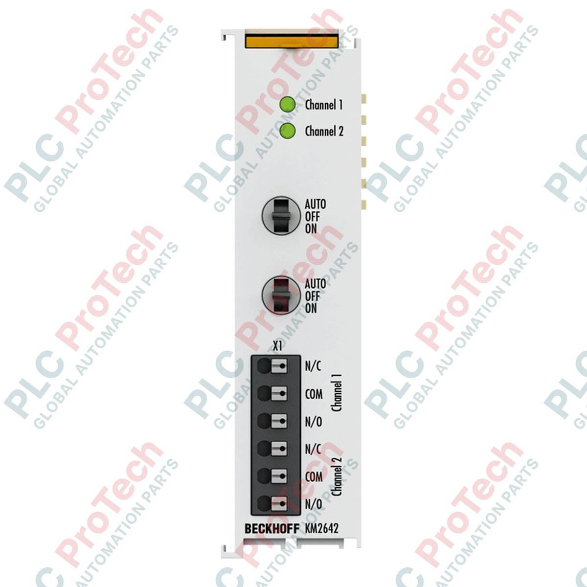
Le Beckhoff KM2642 (KM2642) est un module terminal relais de sortie numérique à 2 canaux haute capacité conçu pour le système modulaire d'E/S K-bus de Beckhoff. Déployé dans les installations environnementales des bâtiments, les circuits logiques critiques des installations CVC et les réseaux de contrôle d'éclairage automatisé, ce terminal spécialisé dispose d'interrupteurs d'override manuel/automatique intégrés sur la face avant. Cette configuration matérielle permet aux ingénieurs de maintenance de forcer physiquement les états des relais lors de la mise en service sur site ou en cas d'override d'urgence, permettant un diagnostic système local direct sans nécessiter l'exécution d'un programme maître PLC actif.
Profil électrique et dynamique des contacts
Ce terminal de bus intègre deux relais inverseurs indépendants (SPDT) configurés pour commuter des potentiels en courant alternatif jusqu'à une tension nominale de 230 V AC, avec un seuil de pic de commutation absolu de 250 V AC. Construit avec une métallurgie de contact en oxyde d'argent-étain ($\text{AgSnO}_2$) très durable pour résister au transfert de matière et à l'érosion par arc, chaque canal indépendant supporte un courant électrique continu allant jusqu'à 6 A. L'infrastructure des contacts accepte des charges ohmiques, inductives et capacitives pour lampes, supportant des surtensions de démarrage à fort appel jusqu'à 10 A provenant de ballasts électroniques tout en maintenant une consommation de courant opérationnelle minimale de 130 mA depuis le bus numérique K-bus.
Matrice de performance technique
| Paramètre principal |
Spécification fonctionnelle |
| Numéro de modèle |
KM2642 |
| Marque |
Beckhoff Automation |
| Origine |
Allemagne |
| Classification du module |
Module relais manuel/automatique pour bornier K-Bus |
| Configuration de sortie |
2 ensembles de contacts inverseurs (SPDT Form C) |
| Tension nominale maximale |
230 V AC (maximum absolu 250 V AC) |
| Capacité de courant continu |
6 A par canal indépendant |
| Puissance de commutation maximale |
1,5 kVA |
| Charge minimale requise |
100 mA à 12 V |
| Tolérances d'appel de courant ballast |
Pic de courant de démarrage max. 10 A |
| Composition des contacts |
Oxyde d'argent-étain ($\text{AgSnO}_2$) |
| Empreinte dans l'image de processus |
2 entrées numériques (rétroaction) / 2 sorties numériques |
| Durée de vie mécanique |
Minimum 1 x $10^6$ opérations |
| Durée de vie électrique |
Minimum 1 x $10^5$ opérations (3 A / 250 V AC) |
| Consommation de courant logique K-Bus |
Typiquement 130 mA |
| Température de fonctionnement |
0 à +55 °C (sans condensation) |
| Température de stockage |
-25 à +85 °C |
| Protection contre les infiltrations |
Boîtier de type ouvert IP20 |
| Poids net de l'ensemble |
env. 110 g |
| Poids brut d'expédition |
3,0 kg (emballé dans un conditionnement industriel en grande quantité) |
Diagnostics industriels et FAQ
Comment les interrupteurs à bascule manuels interagissent-ils avec l'image de processus TwinCAT ?
Les interrupteurs en façade dirigent physiquement le chemin du signal de commande. En position "Auto", l'état du relais est déterminé par les 2 bits de sortie numérique mappés dans l'image de processus TwinCAT. En position "Manuel (ON/OFF)", la position physique du contact change indépendamment des commandes du contrôleur. Le module renvoie 2 bits d'entrée numérique à l'image de processus du PLC pour informer le code applicatif si le relais est activement alimenté ou désactivé, assurant une surveillance complète de la boucle.
Quelles sont les causes de soudure prématurée des contacts sur un canal relais prévu pour 6 A ?
La dégradation prématurée des contacts provient généralement de courants d'appel inductifs ou capacitifs non atténués. Bien que le matériau $\text{AgSnO}_2$ supporte des charges résistives continues de 6 A, les drivers LED haute efficacité ou les bobines solénoïdes inductives génèrent des courants de démarrage transitoires dépassant le seuil ballast de 10 A. Pour prolonger la durée de vie du module, installez des snubbers RC externes sur les charges inductives AC ou appliquez des limiteurs de courant d'appel dédiés.
Une adresse matérielle est-elle requise lors de l'ajout de ce module à un segment de terminal ?
Non. Le KM2642 ne nécessite ni calcul manuel d'adresse ni réglage physique de commutateurs DIP. Le module s'identifie automatiquement auprès du coupleur de bus en amont (tel que BK1120 ou BK9000) lors de l'initialisation, mappant sa configuration interne de registre 2 entrées et 2 sorties directement dans le flux binaire K-bus selon sa position physique sur la pile de rails DIN.
Mise en service sur site et consignes de câblage
-
Attribution des chemins de contact à changement de position : Vérifiez la disposition des affectations des bornes avant de connecter les conducteurs AC sous tension. Comme il s'agit de contacts à changement de position véritables, chaque canal dispose d'un chemin Commun (C), Normalement Ouvert (NO) et Normalement Fermé (NC). Assurez-vous que la ligne de charge est connectée à la broche correcte pour éviter un fonctionnement inverse lors du passage entre les modes automatique et manuel.
-
Suppression d'arc inductif : Lors de l'utilisation de la borne pour commuter des charges inductives—comme des bobines de contacteurs brutes, des solénoïdes de frein mécanique ou de petits moteurs de pompe monophasés—branchez toujours un parasurtenseur externe en parallèle avec la charge. Cela atténue les pics de tension de force contre-électromotrice lors de l'ouverture des contacts, empêchant les arcs à haute tension sur les contacts en oxyde d'étain argenté et évitant l'injection de bruit électromagnétique dans le rail K-bus.
-
Mise à la terre sur rail DIN et dégagements thermiques : Fixez solidement le châssis IP20 sur des rails DIN TS35 standard, en veillant à ce que les contacts du bus de données interne s'engagent correctement avec les tranches adjacentes. Montez l'ensemble horizontalement dans un boîtier bien ventilé. Maintenez un dégagement d'air vertical minimum de 30 mm au-dessus et en dessous du bloc de modules pour assurer un refroidissement convectif optimal dans sa plage de fonctionnement de 0 à +55 °C.