Présentation du produit
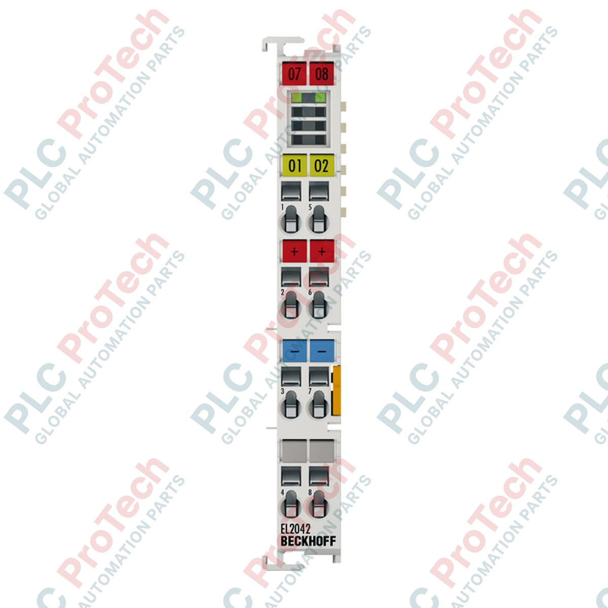
Le EL2042 (EL2042) est un terminal de sortie numérique 2 canaux à haute capacité conçu pour le système EtherCAT I/O, spécialement destiné à piloter des charges industrielles lourdes. Alors que les terminaux de sortie standard atteignent souvent un pic de 0,5 A, le EL2042 délivre un courant robuste de 4,0 A par canal, ou jusqu’à 8,0 A en connexion parallèle. Dans des applications exigeantes telles que le contrôle de vannes hydrauliques, les démarreurs de gros moteurs DC et les éléments chauffants à haute intensité, ce terminal fournit la puissance nécessaire sans besoin de relais intermédiaires. Doté de diagnostics avancés pour la détection de court-circuit et de circuit ouvert, l’EL2042 améliore la fiabilité du système en fournissant un retour en temps réel au contrôleur, réduisant ainsi considérablement le temps de dépannage dans les opérations de fabrication 24/7.
Configuration technique
L’EL2042 utilise une technologie de connexion 3 fils, permettant la connexion directe des charges sans blocs de jonction supplémentaires pour la terre ou la distribution d’alimentation. Les étages de sortie sont entièrement protégés contre les courts-circuits et conçus pour gérer aisément des charges ohmiques, inductives et des lampes. Une caractéristique technique remarquable est sa haute énergie de coupure de < 1,7 J par canal, ce qui lui permet de dissiper en toute sécurité l’énergie stockée dans de grandes bobines inductives lors de la coupure. Le module fonctionne avec un temps de réponse rapide (TON : 40 µs) et offre une isolation électrique de 500 V entre la logique E-bus et le potentiel de terrain. Son design compact à haute densité s’intègre dans un boîtier standard de 12 mm, conservant l’empreinte compacte du bloc terminal EtherCAT tout en délivrant une puissance significative.
Caractéristiques techniques
| Caractéristique |
Spécification |
| Modèle |
EL2042 |
| Marque |
BECKHOFF |
| Nombre de sorties |
2 |
| Courant de sortie max. |
4,0 A par canal (8,0 A en parallèle) |
| Type de connexion |
3 fils |
| Tension nominale |
24 V DC (-15 % / +20 %) |
| Énergie de coupure |
< 1,7 J par canal |
| Diagnostics |
Court-circuit et circuit ouvert |
| Consommation E-bus |
Typ. 120 mA |
| Temps de commutation |
Typ. TON : 40 µs, TOFF : 200 µs |
| Dimensions (L x H x P) |
12 mm x 100 mm x 68 mm |
| Température de fonctionnement |
-25 à 60 °C |
FAQ techniques
Comment configurer le terminal pour une opération parallèle à 8,0 A ?
Pour obtenir une sortie de 8,0 A, les deux canaux de sortie doivent être câblés en parallèle vers la même charge et commutés simultanément dans le programme PLC TwinCAT. Étant donné que l’EL2042 est protégé contre les courts-circuits et dispose d’une capacité de commutation synchronisée, il peut partager en toute sécurité le courant de charge entre les deux interrupteurs semi-conducteurs internes.
Quel est l’avantage du diagnostic intégré de « circuit ouvert » ?
La fonction de diagnostic de circuit ouvert permet au PLC de détecter si un fil est coupé ou si une charge (comme une bobine de solénoïde) est défaillante, même lorsque la sortie est en état « OFF ». Cela permet une alerte immédiate avant que la machine ne lance un cycle, évitant ainsi des dommages mécaniques potentiels ou des cycles de production gaspillés.
Ce terminal nécessite-t-il une alimentation séparée ?
L’EL2042 puise son courant de sortie à partir des contacts d’alimentation du bloc terminal EtherCAT. Compte tenu de sa capacité de courant élevée (jusqu’à 8,0 A), il est essentiel de s’assurer que le terminal d’alimentation précédent (comme un EL9100 ou EK1100) et la charge totale sur le rail de contact d’alimentation ne dépassent pas la limite maximale de 10 A.
Guide d’ingénierie et d’installation
-
Gestion thermique : Lors de l’utilisation des deux canaux à la capacité maximale de 4,0 A, le terminal génère de la chaleur interne. Assurez-vous que l’armoire de commande dispose d’une ventilation adéquate et que la température de fonctionnement ne dépasse pas 60 °C. Si plusieurs unités EL2042 sont utilisées côte à côte à pleine charge, envisagez l’utilisation d’un ventilateur ou un espacement pour éviter les déclenchements thermiques.
-
Exigences de câblage : En raison du courant de 4,0 A par canal, assurez-vous que la section des fils utilisés est suffisante pour éviter les chutes de tension. Le terminal supporte jusqu’à 2,5 mm² (AWG 14) pour les fils rigides ou souples. L’utilisation de manchons isolants de 1,5 mm² est recommandée pour les conducteurs flexibles afin d’assurer une connexion résistante aux vibrations.
-
Protection des charges inductives : Bien que l’EL2042 ait une énergie de coupure élevée de 1,7 J, les charges inductives très importantes (comme les gros électroaimants de frein) peuvent encore générer une force contre-électromotrice significative. Dans ce cas, l’installation d’une diode de roue libre externe directement sur la charge peut aider à protéger les composants internes du terminal et à réduire les interférences électromagnétiques (EMI).