Description
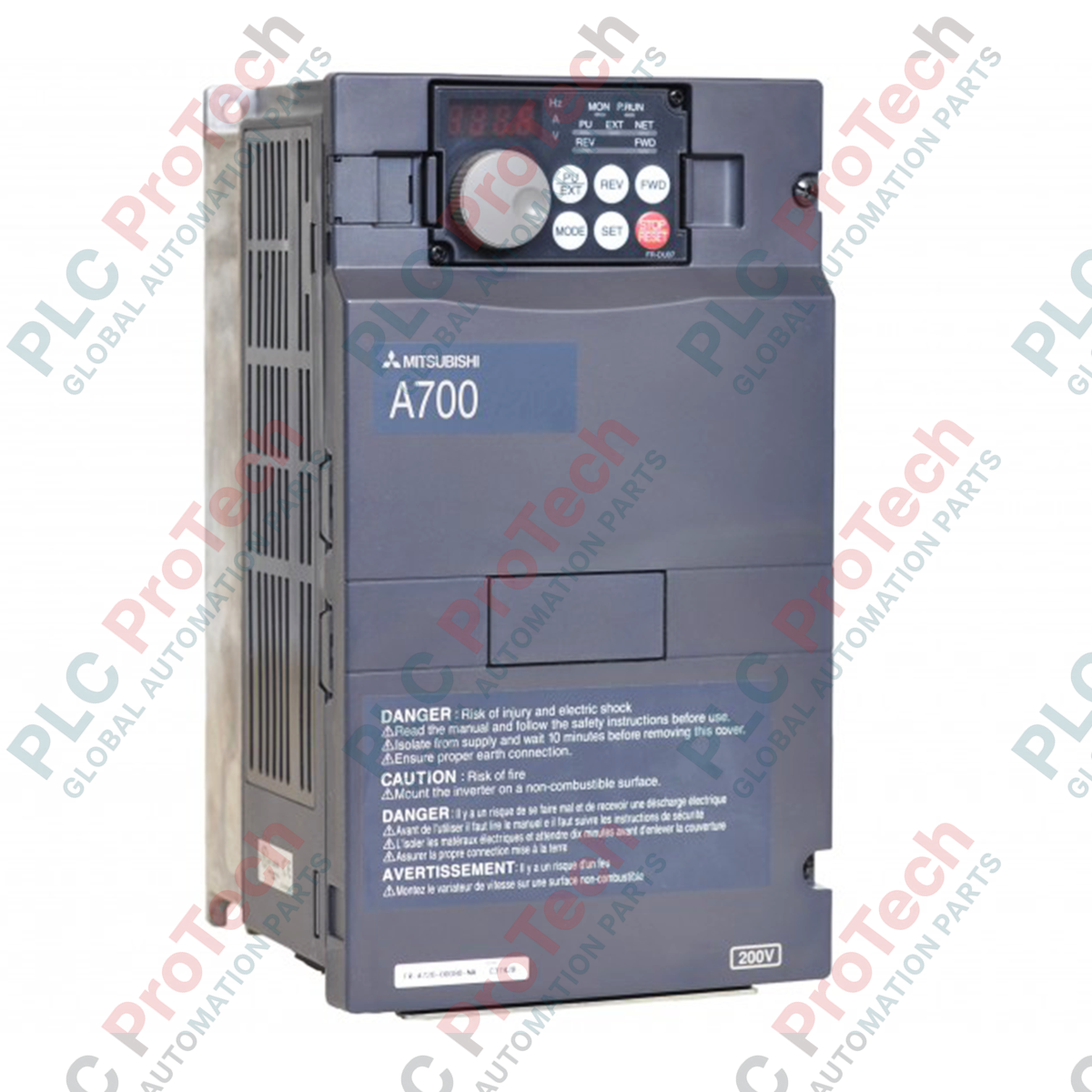
Designed for exceptional motor control in high-demand environments, the Mitsubishi Electric FR-A740-22K-CHT provides precise variable frequency speed and torque management for three-phase induction motors. As a part of the high-performance A700 Series, this 22 kW drive features advanced vector control algorithms and robust electrical protections. It is built to ensure seamless operation under continuous heavy-duty loads while maintaining excellent thermal efficiency.
Key Technical Features
-
Advanced Vector Control: Supports offline/online auto-tuning for premium flux vector performance without speed sensors.
-
High Overload Threshold: Tolerates transient current surges up to 150% for 60 seconds and 200% for 3 seconds to protect against mechanical blockages.
-
Continuous Thermal Capacity: Engineered with forced-air fan cooling to support full-load operations up to an ambient temperature of 50 degC.
-
IP20 Enclosed Protection: Compact housing designed for integration into standard industrial cabinets and control rooms.
Industrial Applications
- Heavy manufacturing machinery including extruders, mixers, and rotary kilns.
- High-inertia material handling systems, industrial conveyors, and automated cranes.
- Large centrifugal fans, exhaust blowers, and municipal booster pumps.
Technical Specifications
| Manufacturer |
Mitsubishi Electric |
| Model Number |
FR-A740-22K-CHT |
| Series Type |
A700 Series |
| Applicable Motor Capacity |
22 kW |
| Rated Output Current |
44 A |
| Rated Capacity |
32.8 kVA |
| Rated Voltage (Output) |
Three-phase 380V to 480V |
| Rated Input AC Voltage / Frequency |
Three-phase 380V to 480V, 50Hz/60Hz |
| Permissible AC Voltage Fluctuation |
323V to 528V, 50Hz/60Hz |
| Permissible Frequency Fluctuation |
+/- 5% |
| Power Supply Capacity |
41 kVA |
| Protective Rating |
IP20 Enclosed Type |
| Cooling Method |
Forced Air Cooling |
| Country of Origin |
Japan |
| Shipping Weight (Calculated) |
14.0 kg |
| Package Dimensions (Calculated) |
430 x 290 x 260 mm |
Power and Control Terminals
| Terminal Symbol |
Terminal Name |
Functional Assignment |
| R/L1, S/L2, T/L3 |
AC Power Input |
Connection to commercial three-phase mains supply. |
| U, V, W |
Inverter Output |
Connection to the external three-phase induction motor. |
| P/+, PR |
Braking Resistor |
Connection point for dynamic braking options. |
| STF / STR |
Forward / Reverse Start |
External signal command triggers for directional rotation. |
| SD |
Signal Common (Sink) |
Common ground terminal for digital inputs configured to sink logic. |
Empirical Engineering Insights
Alternative Models & Compatibility
The "CHT" suffix designates a localized firmware and default parameter configuration optimized for standard Asian markets, meaning the default base frequency is 50Hz and digital control terminals default to sink (negative) logic. This drive is a direct drop-in replacement for standard FR-A740-22K units, provided parameters like Pr. 3 (Base Frequency) and the internal logic jumper are verified and calibrated to your local wiring standards.
Application Pitfalls & Engineering Notes
For dynamic systems with highly cyclical braking or large physical inertia, the drive's built-in 20% torque permissible duty might trigger regenerative overvoltage faults (E.OV3). Integrating a dedicated external dynamic braking unit (such as the FR-BU2 series) alongside dynamic resistors is highly recommended to protect the internal DC bus. When mounting inside completely closed IP54 panels, ensure cabinet dimensions allow the dissipation of approximately 650 Watts of thermal energy produced by the drive at full load.
Commissioning & Wiring Tips
Always isolate the control signaling cable from high-voltage motor output lines by keeping a separation distance of at least 10 cm, or utilize dedicated metal conduit separation. For analog control signals (terminals 2, 4, 1), use shielded twisted-pair cabling and tie the shield to control ground (terminal 5) at the drive end only. This mitigates high-frequency noise from corrupting speed references.
Installation Guidelines
CRITICAL SAFETY WARNING:
Ensure all primary AC feed lines are de-energized prior to beginning installation. The internal DC bus capacitors contain dangerous residual charge. Wait a minimum of 10 minutes after disconnecting power, and confirm the physical "CHARGE" LED on the control board is fully extinguished before performing any terminal modifications or wire connections.
1
Vertical Orientation: Always mount the drive vertically inside the panel to leverage built-in forced-air convection dynamics.
2
Clearance Tolerances: Maintain at least 100 mm of open vertical space above and below the device, and a minimum of 50 mm horizontal distance from side components.
3
Protective Earthing: Connect the dedicated ground terminal (PE) to an active system ground. Keep grounding resistance below 10 ohms to prevent electrostatic interference.