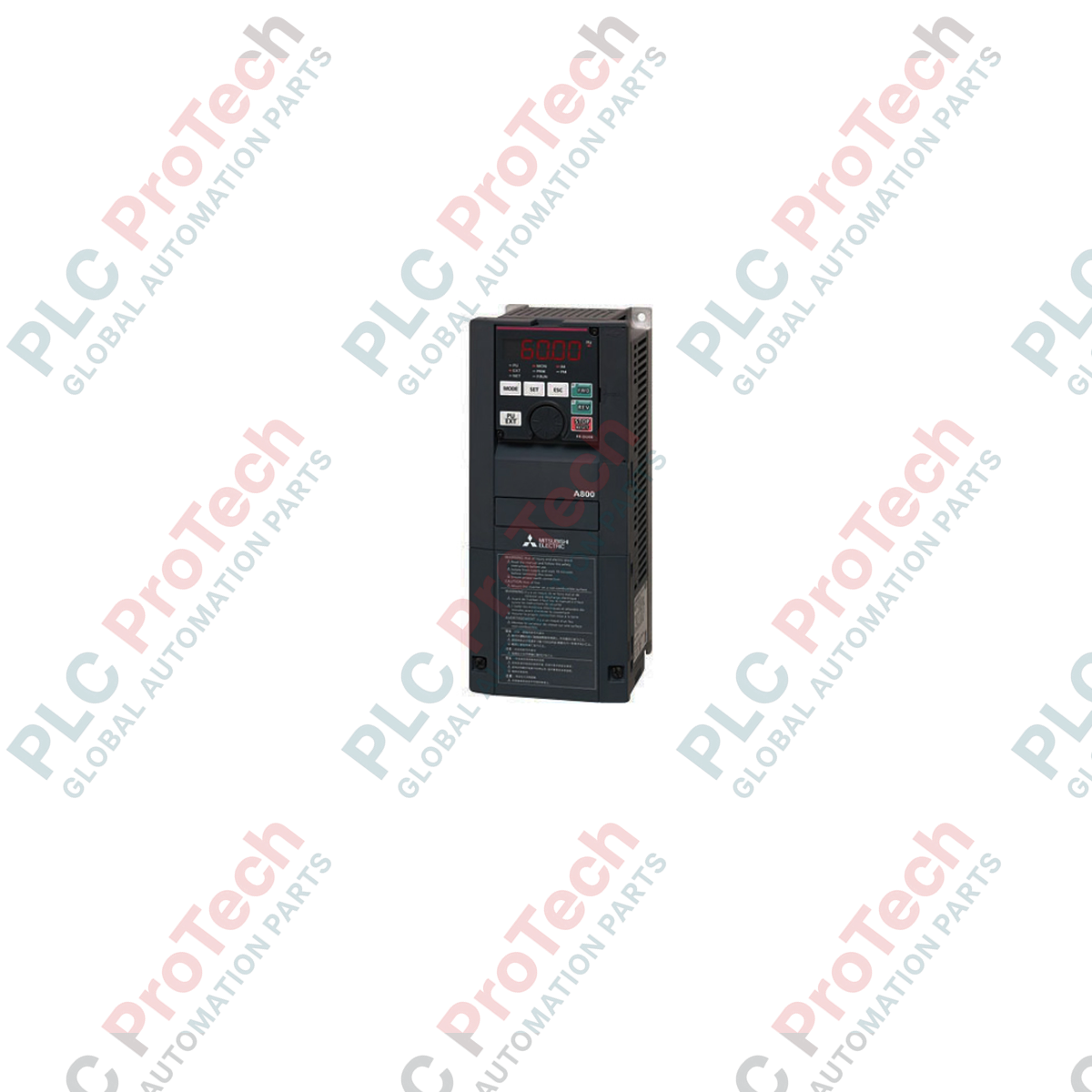
Description
Designed for heavy-duty industrial motor control, the Mitsubishi Electric FR-A820-18.5K delivers precise speed and torque regulation across high-demand automation architectures. Operating on a three-phase input, this high-performance variable frequency drive features advanced vector control algorithms to optimize motor efficiency and system reliability. Designed for integration into demanding environments, its robust electrical design accommodates voltage fluctuations and handles high load dynamics, making it an essential component for critical machinery and process control systems.
Features
- Real sensorless vector control and perfect closed-loop vector control capability.
- Robust tolerance to line voltage fluctuations, maintaining stable output under varying grid conditions.
- Excellent low-speed torque performance for demanding startup conditions.
- Integrated diagnostic and safety features to minimize operational downtime.
- Compact IP20 enclosure designed for space-saving panel installation.
Applications
- Heavy-duty conveyors and material handling systems requiring high starting torque.
- Industrial fans, blowers, and positive displacement pumps.
- Extruders, mixers, and centrifuges in chemical and plastics processing.
- Metalworking machinery, cranes, and hoisting equipment.
Technical Specifications
| Manufacturer |
Mitsubishi Electric |
| Model Number |
FR-A820-18.5K |
| Series |
FREQROL-A800 |
| Product Type |
Variable Frequency Drive (VFD) Inverter |
| Rated Input Voltage |
Three-phase 200 to 240 VAC |
| Rated Input Frequency |
50 Hz / 60 Hz |
| Permissible AC Voltage Fluctuation |
170 to 264 VAC |
| Permissible Frequency Fluctuation |
+/- 5% |
| Enclosure Rating |
IP20 |
| Shipping Weight |
16.5 kg |
Empirical Engineering Insights
Alternative Models & Compatibility
This unit serves as a functional upgrade path for legacy FR-A720-18.5K models. While physical dimensions and mounting holes are highly compatible, terminal configurations and control logic terminal layouts should be cross-referenced. Parameter sets can be migrated efficiently using FR Configurator2 software via the USB port.
Application Pitfalls & Engineering Notes
In enclosed control cabinets, this IP20 unit dissipates considerable thermal energy under full 18.5 kW load. Ensure cabinet cooling fans are sized to handle the drive’s heat loss. To protect the inverter's input rectifier stage, an input AC reactor must be installed if the main power transformer capacity is 500 kVA or more, or if thyristor loads are on the same line.
Commissioning & Wiring Tips
Always use symmetric shielded motor cables grounded at both ends to reduce electromagnetic interference (EMI) and protect motor bearings from capacitive shaft currents. Ensure that the control circuit wiring is routed completely separate from the main circuit power lines to prevent induced signal noise.
Installation Guidelines
CRITICAL WARNING:
Hazard of electrical shock. Ensure all incoming AC mains power is completely isolated and locked out before starting installation. Wait at least 10 minutes after disconnecting power for the internal DC bus capacitors to discharge. Always measure the voltage between terminals P/+ and N/- with a reliable voltmeter to ensure it is below 45 VDC before touching connections.
1
Mount the inverter vertically on a flat, non-combustible surface to ensure proper upward airflow through the cooling heatsink.
2
Connect three-phase AC input power strictly to terminals R/L1, S/L2, and T/L3. Connecting power to output terminals U, V, and W will cause permanent damage to the unit.
3
Verify that the inverter ground terminal is connected to an independent earth ground with low resistance to conform to local safety standards.