Description
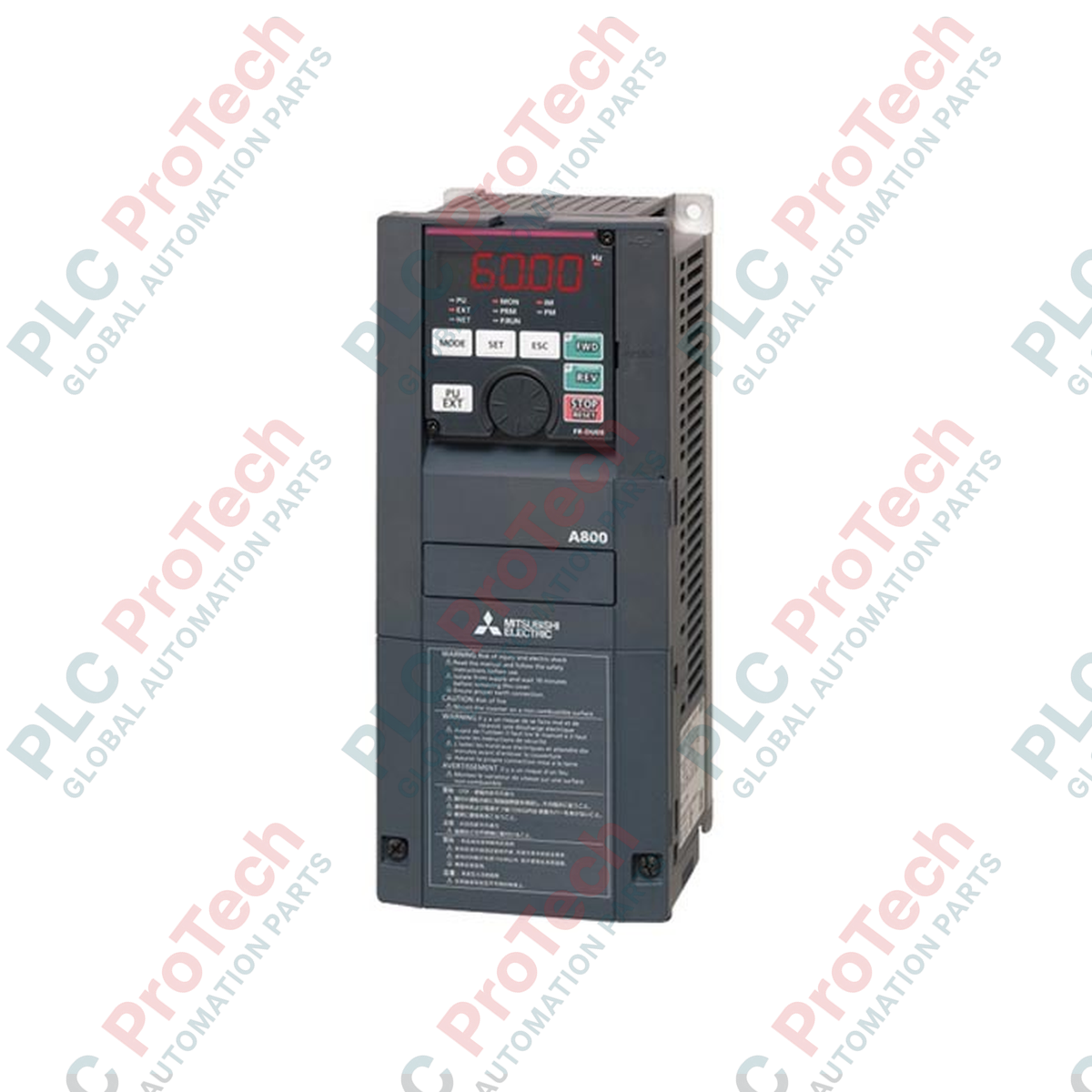
Engineered to meet the demands of heavy-duty industrial motor applications, the Mitsubishi Electric FR-A840-37-1 is a high-performance, three-phase Variable Frequency Drive (VFD) belonging to the premier FR-A800 Series. Designed for robust speed and torque control, this inverter features an integrated FM terminal configuration for high-precision analog pulse train monitoring. Offering seamless integration into existing control architectures, the unit features built-in Modbus RTU protocols and multi-point RS-485 serial interfaces, making it an excellent fit for demanding automation setups requiring exact velocity tracking and high starting torque.
Key Features
-
Real Sensorless Vector Control (RSVC): Delivers exceptional torque performance at near-zero speeds without requiring an external encoder.
-
Flexible Output Frequencies: Supports a wide operating range from 0.2 Hz up to 590 Hz to handle diverse high-speed industrial machinery.
-
FM Control Terminals: Outfitted with dedicated FM pulse-train and analog voltage monitoring channels (0-10Vdc) for precise feedback loop integration.
-
Built-In RS-485 Interface: Built-in support for RS-422 and RS-485 multi-drop communication running native Modbus RTU protocols.
-
IP00 Open-Type Chassis: Built for optimal space-saving layouts within localized, climate-controlled industrial control panels.
Industrial Applications
-
High-Inertia Centrifuges: Manages regenerative energy and deceleration profiles safely.
-
Heavy-Duty Conveyor Systems: Provides high breakaway torque for starting fully loaded belts.
-
Extruders and Mixers: Maintains constant torque control across varying material viscosity ranges.
-
Industrial Fan & Pump Arrays: Reduces energy consumption through precise affinity-law speed regulation.
Technical Specifications
| Parameter |
Value / Specification |
| Manufacturer |
Mitsubishi Electric |
| Model Number |
FR-A840-37-1 |
| Series |
FR-A800 Series |
| Applicable Motor Capacity |
37 kW (50 HP) |
| Supply Voltage (AC) |
3-Phase 380Vac to 500Vac (50/60 Hz) |
| Output Phase |
3-Phase AC |
| Output Frequency Range |
0.2 Hz to 590 Hz |
| Communication Protocols |
Modbus RTU, RS-232, RS-422, RS-485 |
| Analog Output Channels |
1 x Analog Output (0-10Vdc) via FM Terminal |
| Degree of Protection |
IP00 (Open Type) |
| Country of Origin |
Japan |
| Shipping Weight (Calculated) |
43.0 kg (94.8 lbs) |
| Package Dimensions (Calculated) |
490 mm x 300 mm x 250 mm |
Connections and Interfaces
| Terminal Block Designation |
Functional Circuit Assignment |
| R/L1, S/L2, T/L3 |
3-Phase Main AC Power Supply Input |
| U, V, W |
3-Phase Variable Frequency Output to Motor |
| FM |
Pulse train monitor / Analog signal output (0-10Vdc) |
| TXD+ / TXD- / RXD+ / RXD- |
RS-485 / Modbus RTU Communication interfaces |
| SD |
Common Terminal for External Analog Command Reference |
Alternative Models & Compatibility
The FR-A840-37-1 serves as a direct functional replacement for the older generation FR-A740-37K drive variants. If migrating from the A700 series, verify panel space clearances, as physical depths and wiring terminal profiles differ slightly. Configuration and parameter profiles can be fully imported and converted using Mitsubishi Electric's FR Configurator2 software platform to minimize deployment downtime.
Application Pitfalls & Engineering Notes
With a high power rating of 37 kW (50 HP), this drive generates significant heat during continuous full-load operations. It requires installation inside a dedicated, well-ventilated enclosure with a minimum of 100mm clearance on both the top and bottom of the unit. When using the drive in high-duty cycle applications, ensure external braking resistors are sized correctly to prevent overvoltage tripping (E.OV3) during regenerative braking events.
Commissioning & Wiring Tips
To mitigate electromagnetic interference (EMI) issues, run the 3-phase output motor connections (U, V, W) in continuous shielded cable, grounding the shield at both the drive enclosure and the motor terminal box. When implementing serial communications, ensure parameter 117 (Station Number) and parameter 118 (Baud Rate) are mapped correctly prior to initiating cyclic polling over the Modbus network.
Installation Guidelines
CRITICAL WARNING: Hazardous voltages remain present inside the drive capacitor bank for up to 10 minutes after main power is disconnected. Always verify that the charge lamp is fully extinguished and use a calibrated digital multimeter to verify zero DC bus voltage before initiating termination work.
1
Mount the IP00 chassis vertically onto a flat, non-flammable back panel using M6 or M8 mounting screws to allow unobstructed convection currents.
2
Connect the physical system ground to the PE terminals before terminating the main input power lines (R/L1, S/L2, T/L3).
3
Run control signals and analog feedback loops (FM terminal block) through separate metal conduits isolated from heavy AC power wiring.