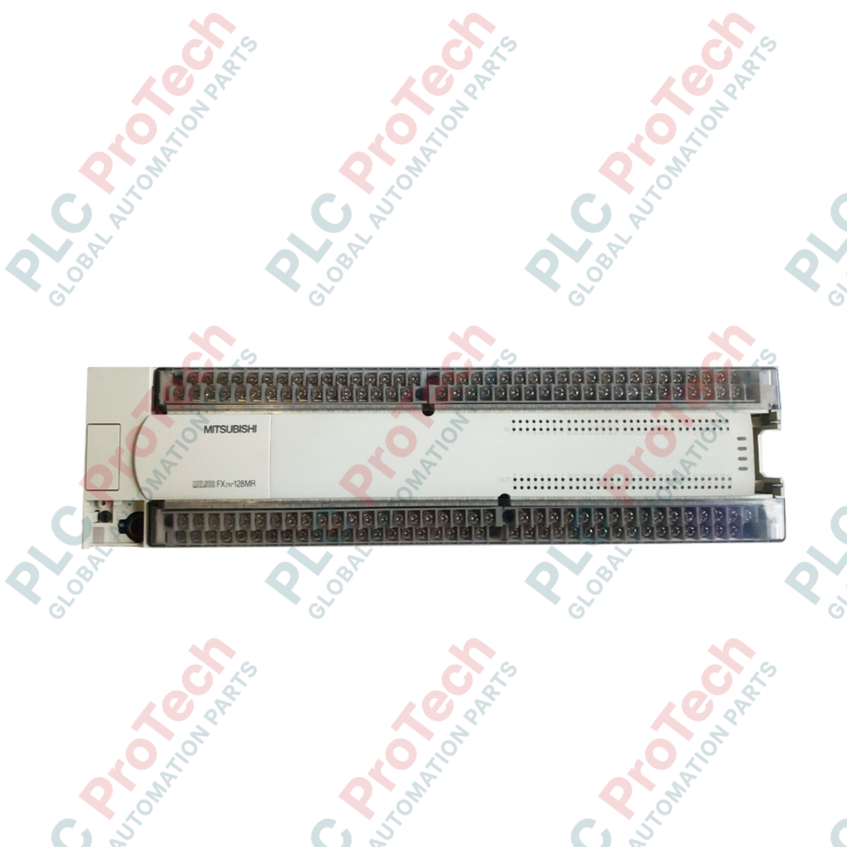
Exécutant des séquences de contrôle à haute densité sur les lignes de fabrication, le Mitsubishi Electric FX2N-128MR-ES/UL fonctionne comme l'unité de base de traitement principale dans l'architecture héritée MELSEC FX2N. Ce contrôleur intègre traitement, alimentation et E/S numériques étendues dans un seul châssis compact, en faisant un choix fiable pour les applications d'automatisation industrielle moyennes à grandes nécessitant des sorties relais robustes et une exécution à grande vitesse.
Caractéristiques principales
- 128 points d'E/S locaux intégrés (64 entrées et 64 sorties relais) extensibles jusqu'à 256 points via des blocs d'extension.
- Alimentation intégrée 100-240V AC avec sortie d'alimentation auxiliaire 24V DC intégrée pour capteurs sur site.
- Contacts de sortie relais électromécaniques évalués à 2A par point, permettant le contrôle direct de contacteurs et solénoïdes.
- Capacité de traitement à grande vitesse avec un temps d'exécution d'instruction de base de 0,08 microseconde.
- Blocs de bornes amovibles facilitant un remplacement rapide sur site et minimisant les temps d'arrêt lors de la maintenance.
Applications
- Systèmes de convoyage et lignes de tri pour la manutention des matériaux.
- Machines d'emballage, stations d'emballage et lignes d'assemblage automatisées.
- Installations de traitement de l'eau, panneaux de contrôle de stations de pompage et gestion des fluides.
- Systèmes CVC, chambres de contrôle environnemental et automatisation des bâtiments.
Spécifications techniques
| Paramètre |
Valeur de spécification |
| Fabricant |
Mitsubishi Electric |
| Numéro de modèle |
FX2N-128MR-ES/UL |
| Série |
MELSEC FX2N |
| Points d'entrée |
64 points (24V DC, sélection Sink/Source) |
| Points de sortie |
64 points (relais) |
| Puissance de sortie |
2A par point, 8A par borne commune (250V AC / 30V DC) |
| Tension d'alimentation |
100 à 240V AC (+10% / -15%), 50/60 Hz |
| Consommation électrique |
100 VA |
| Sortie d'alimentation auxiliaire |
24V DC, 460 mA |
| Capacité du programme |
8k étapes (extensible à 16k étapes avec cassette mémoire) |
| Température de fonctionnement |
0 à 55 °C |
| Température de stockage |
-20 à 70 °C |
| Poids d'expédition (calculé) |
3,0 kg |
| Dimensions de l'emballage (calculées) |
380 x 110 x 110 mm |
Connexions et interfaces
| Borne / Port |
Fonction / Attribution de circuit |
| L, N |
Entrée d'alimentation AC (100 à 240V AC) |
| Borne de terre |
Connexion de terre de protection (PE) |
| 24+, 24- |
Sortie d'alimentation auxiliaire 24V DC (pour excitation de capteurs) |
| S/S |
Borne commune d'entrée (sélection de configuration Sink/Source) |
| X0 à X77 |
Entrées numériques 24V DC (système de numérotation octal) |
| COM0 à COM7 |
Bornes communes de sortie relais isolée |
| Y0 à Y77 |
Bornes de sortie relais (système de numérotation octal) |
Modèles alternatifs et compatibilité
La série FX2N est une gamme de produits ancienne. Pour les modernisations de systèmes, le FX3U-128MR/ES-A est le successeur direct physique et fonctionnel. Il utilise le même encombrement et la même disposition des borniers, bien qu’une conversion de programme via GX Works2 ou GX Developer soit nécessaire pour compiler le jeu d’instructions FX2N vers la nouvelle architecture FX3U.
Pièges d’application et notes d’ingénierie
Les charges inductives telles que les solénoïdes, bobines de contacteurs et vannes magnétiques génèrent une force électromotrice inverse importante lors de leur coupure. Pour éviter le soudage prématuré des contacts et la dégradation de la résistance de contact des relais internes, installez toujours des suppressions RC externes pour les charges AC ou des diodes de roue libre pour les charges DC. De plus, assurez-vous que le courant total prélevé sur la borne auxiliaire 24V DC ne dépasse pas 460 mA, car une surcharge de cette borne déclenchera la protection interne contre les surintensités et coupera les circuits d’entrée.
Conseils de mise en service et de câblage
Lors du câblage des entrées numériques, configurez la borne S/S selon votre type de capteur. Reliez la borne S/S à la borne 24V pour une configuration d’entrée Sink (capteurs NPN) ou à la borne 0V pour une configuration d’entrée Source (capteurs PNP). Évitez de faire passer les câbles de signaux E/S dans le même conduit ou goulotte que les lignes haute tension afin d’éviter que les interférences électromagnétiques ne corrompent les signaux d’entrée.
Consignes d’installation
AVERTISSEMENT CRITIQUE
Isolez toutes les sources d’alimentation externes avant toute installation, câblage ou remplacement de module. Les charges résiduelles dans les condensateurs internes peuvent présenter un risque de choc électrique. Assurez-vous que l’unité est montée dans une armoire bien ventilée pour éviter l’accumulation thermique.
1
Fixez solidement l’unité de base PLC sur un rail DIN de 35 mm ou directement sur la plaque arrière de l’armoire en utilisant les trous de fixation intégrés.
2
Reliez la borne de terre de protection (PE) au barreau de terre principal du système avec un fil d’une section d’au moins 2,0 mm².
3
Raccordez les lignes d’alimentation AC (100-240V AC) aux bornes L et N en utilisant des embouts à sertir pour éviter que des brins desserrés ne provoquent des courts-circuits.
4
Vérifiez que la configuration du cavalier des bornes S/S correspond à la logique de votre capteur de terrain (NPN ou PNP) avant d’alimenter l’appareil.